Installation, Installing tsunami in a dcc-ready model – SoundTraxx Tsunami Quick Start User Manual
Page 12
Tsunami Quick Start Guide
Page 9
Tsunami Quick Start Guide
Page 9
Installing Tsunami in a DCC-ready Model
If your locomotive is wired with an NMRA-compatible 8-pin socket, you may
solder a mating connector to the DSD’s wire harness, which will allow you to
easily install the decoder by simply plugging the connector into the socket,
with the exception of the connections for Functions 5 and 6, the speaker and
the exhaust cam. SoundTraxx offers P.N. 810123, which is a package of four
connectors that meet NMRA specifications.
1. Remove the ‘dummy’ plug from the NMRA socket.
2. We highly recommend you test the socket itself to ensure it is properly
wired. Assuming the locomotive manufacturer wired the socket correctly
can be dangerous! If you don’t know how to do this, see the
Installation
Guide.
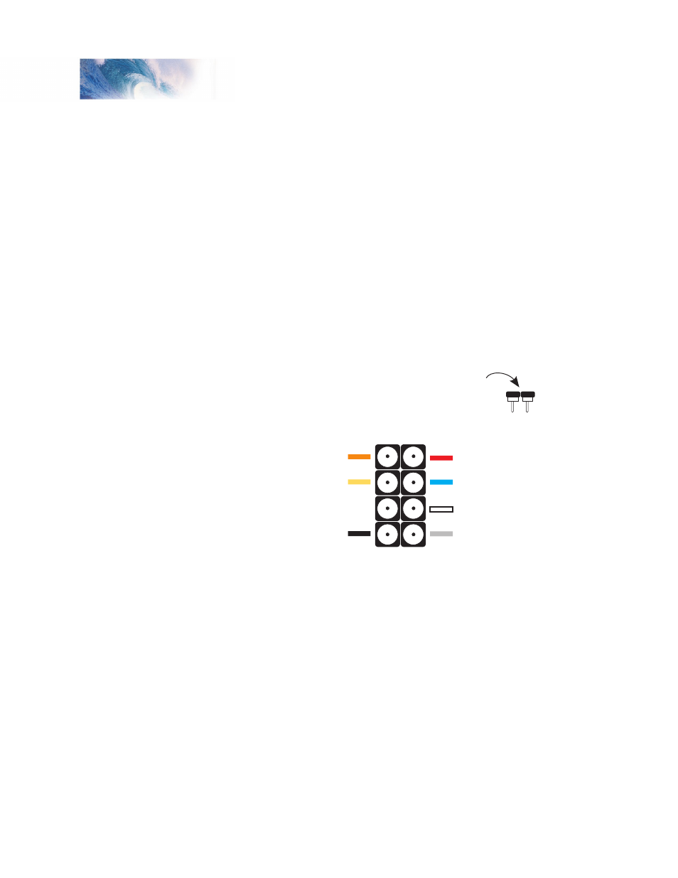
3. Wire the connector to the decoder’s wire harness according to the
illustration. Solder the wires from the sound decoder to the cup side of
the connector as shown in the Figure 2.
Figure 2 - NMRA 8-Pin Connector Wiring Code
4. Plug the newly wired connector into the socket with the orange wire
at pin 1 on the manufacturers circuit board. Most manufacturers have
labeled the sockets with pin 1 or pin 8 (at a minimum). Once you have
plugged in the 8-pin connector, you will still need to wire the speaker and
cam according to the instructions for a non DCC-ready model.
Installation
Solder wires to ‘cup’ side
of 8-pin connector
Motor Right (Orange)
Rear Light (Yellow)
Not Used
Left Rail (Black)
Right Rail (Red)
Function Common (Blue)
Headlight (White)
Motor Left Gray
Pin 1 Pin 8
Pin 4 Pin 5