Installation, Wiring the decoder, Track connections – SoundTraxx Tsunami Quick Start User Manual
Page 10: Motor connections, Speaker connections
Tsunami Quick Start Guide
Page 7
Tsunami Quick Start Guide
Page 7
Wiring the Decoder
Begin by mounting the speaker and securing the decoder in place using
double-sided foam tape. Temporarily refit the body shell to ensure that
adequate clearance still exists.
When wiring the decoder, trim all wires to reduce unnecessary lead length.
This will not only give your installation a neater appearance but also prevent
wires from interfering with the drive mechanism and getting pinched when
closing up the boiler, tender or body shell.
Track Connections
Connect the RED wire to the right (engineer’s side) track power pickup and
the BLACK wire to the left track power pickup. If your model is DCC-ready,
i.e. there is an eight-pin DCC socket already wired to the motor, follow the
instructions on page 9 for your track and motor connections.
Motor Connections
Connect the ORANGE wire to the motor’s (+) terminal and the GRAY wire to
the motor’s (-) terminal.
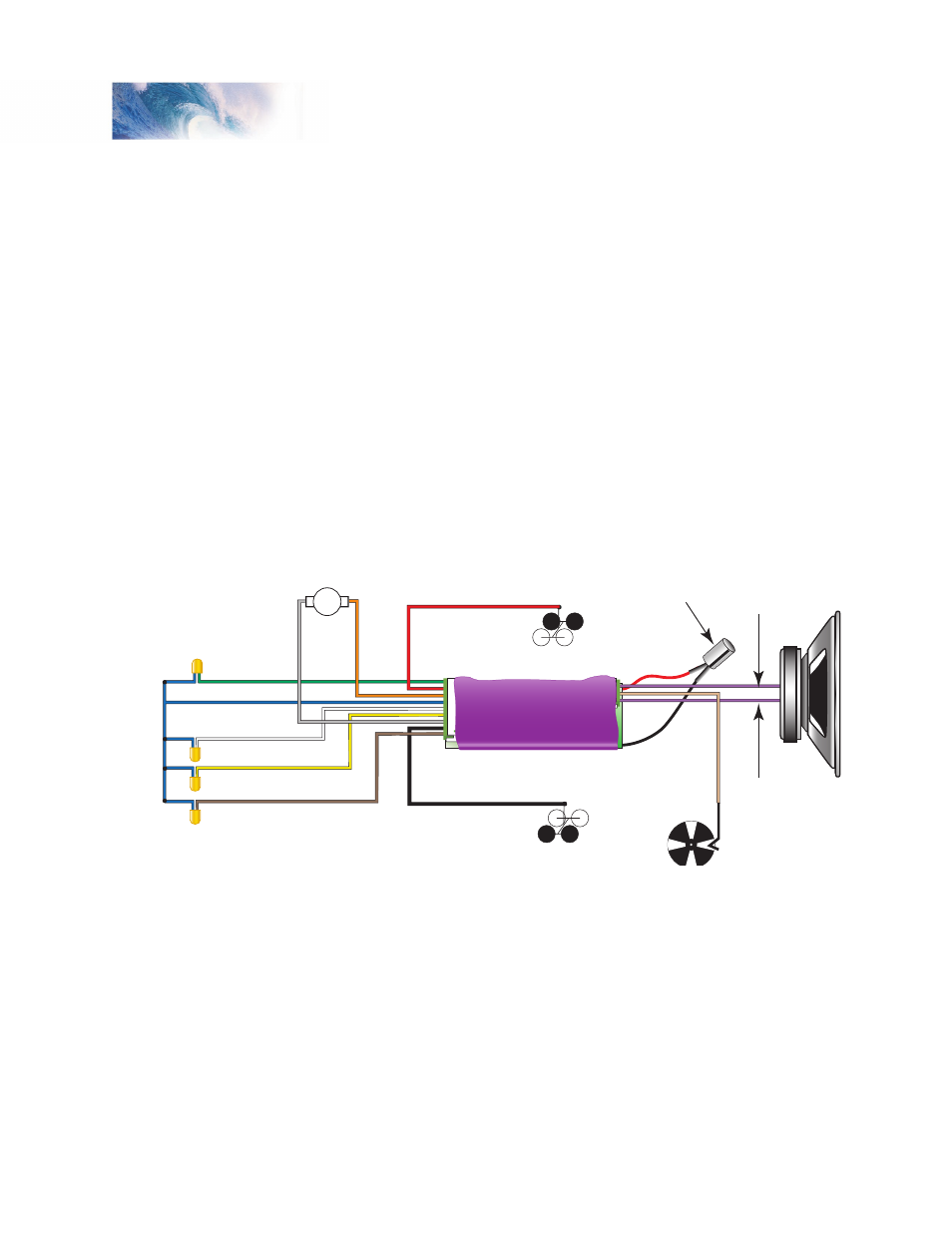
Figure 1 - Wiring Diagram
Speaker Connections
Note: Tsunami is designed to operate with speakers having an impedance
of 8 ohms or higher. Using a speaker impedance less than 8 ohms may
result in erratic operation or even component failure!
Connect the decoder’s PURPLE speaker (+) wire (pin 12) to one of the
speaker terminals. Connect the other PURPLE speaker (-) wire (pin 10) to
the other speaker terminal.
Note: Tsunami does not need a capacitor to be wired in series with the
speaker as required by some other SoundTraxx decoders.
Installation
Speaker
Minus (-)
(Purple)
Headlight (White)
Backup Light (Yellow)
Function Common (Blue)
Function 5 Output (Brown)
Function 6 Output (Green)
Motor - (Gr
ay
)
M
ot
or
+
(
O
ra
ng
e)
Left-hand Rail Pickup (Black)
Right-hand Rail Pickup (Red)
Speaker
Plus (+)
(Purple)
Capacitor
Exhaust Cam
(Optional)
(Tan)