Sim2 HT300 E-Link User Manual
Page 33
33
����������
Screen
Screen
size width
(diagonal)
min. L
H max
max. L H max
Min projection distance
16/9
2,7
9’ 0”
3,3
10’ 9”
3,8
12’ 7”
4,4
14’ 4”
4,9
16’ 2”
5,5
17’ 11”
6,6
21’ 7”
8,2
26’ 11”
9,9
32’ 4”
11,0
35’ 11”
12,0
39’ 6”
13,7
44’ 11”
1,1
44”
1,3
52”
1,6
61”
1,8
70”
2,0
78”
2,2
87”
2,7
105”
3,3
131”
4,0
157”
4,4
174”
4,9
192”
5,5
218”
m
in.
m
ft. in.
m
ft. in.
0,3
0’ 11”
0,3
1’ 1”
0,4
1’ 3”
0,4
1’ 6”
0,5
1’ 8”
0,6
1’ 10”
0,7
2’ 3”
0,8
2’ 9”
1,0
3’ 4”
1,1
3’ 8”
1,2
4’ 1”
1,4
4’ 7”
m
ft. in.
m
ft. in.
0,3
1’ 0”
0,3
1’ 1”
0,4
1’ 4”
0,5
1’ 8”
0,5
1’ 9”
0,6
2’ 0”
0,7
2’ 4”
0,9
2’ 11”
1,0
3’ 3”
1,2
3’ 11”
1,3
4’ 3”
1,4
4’ 7”
2,0
6’ 6”
2,4
7’ 10”
2,8
9’ 1”
3,2
10’ 5”
3,6
11’ 9”
4,0
13’ 1”
4,8
15’ 8”
6,0
19’ 7”
7,2
23’ 6”
8,0
26’ 1”
8,8
28’ 9”
9,9
32’ 7”
50”
60”
70”
80”
90”
100”
120’
150”
180”
200”
220”
250”
in.
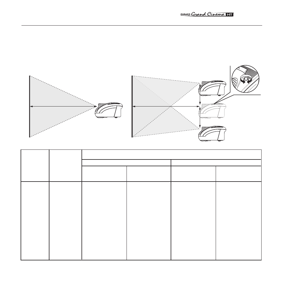
C PROJECTION DISTANCES
Follow the table below to determine the optimal projection distance “L” between the screen and the center of the lens ( Fig.32a).
This will help you to obtain the desired screen size.The manual lens shift adjustments allows the projected image to be moved
vertically, up or down, in relation to the centre of the screen ( Fig.32a). If the distance “H” between the centre of the screen and
the centre of the lens exceed Hmax (see table below), it is necessary to tilt the projector and use the digital keystone to correct
the image projected.
H
H
L
L
( Fig.32a)
( Fig.32b)
Max projection distance