Jumper locations, Jp1 — local termination jumper, Rv2 — gain adjustment – Sierra Video UDA-8705A User Manual
Page 18: Leds
3-2
• User Controls
UDA-8705A User Manual (Rev. 1.1)
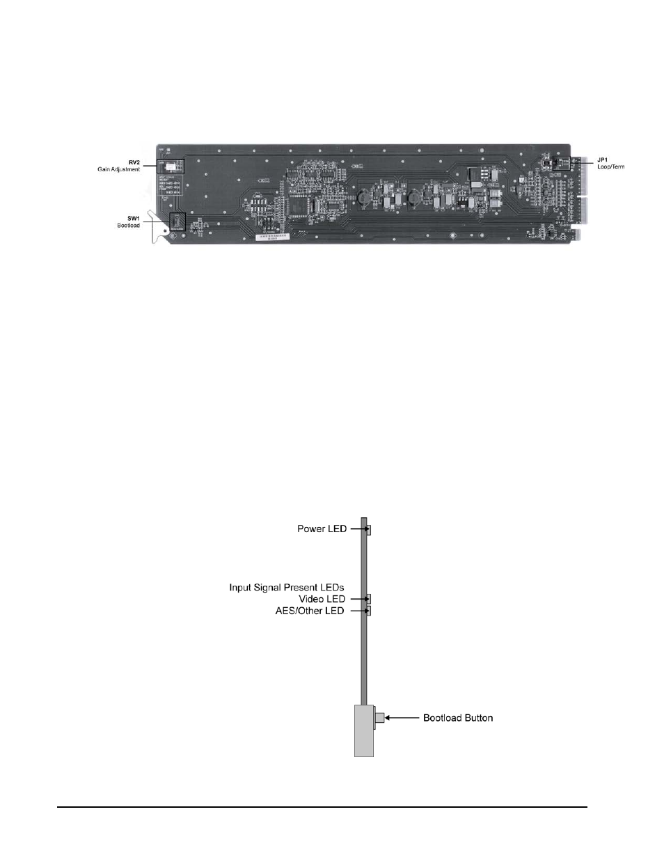
Jumper Locations
The following sections describe the jumpers on the UDA-8705A.
Figure 7. Jumper Locations
JP1 — Local Termination Jumper
The position of JP2 selects an optional 75ohm termination on the input of the UDA-8705A card.
Select one of the following options:
• TERM — Install the jumper in this position to terminate the input signal on this
card. This is the default setting.
• LOOP — Install the jumper in this position to leave the input unterminated. For
example, configure this setting if you wish to loop the signal to another device.
RV2 — Gain Adjustment
The rotation of RV2 adjusts the Gain level of the UDA-8705A and provides a gain range of +/- 3dB.
LEDs
The following sections describe the UDA-8705A LEDs. Refer to Figure 8 for LED locations.
Figure 8. LED Locations
- 1616HD-3G (70 pages)
- RCP-7272 (50 pages)
- Shasta Series 32 (78 pages)
- Pro Series 16 (72 pages)
- Viper Component Series (104 pages)
- SCW-116 (26 pages)
- SCP-224 (18 pages)
- Crestron E-Server 908012 (32 pages)
- 507105-00 (3 pages)
- 507109-00 (5 pages)
- 507112-xx (3 pages)
- 507125 (12 pages)
- 507141 (5 pages)
- 507144-00 (10 pages)
- 587144-00 (5 pages)
- 807121-00 (5 pages)
- 804711-00 (14 pages)
- ADC-107 (23 pages)
- ADA-108 (28 pages)
- EMD-218 (29 pages)
- ADC-142 (29 pages)
- ADM-188 (23 pages)
- ADC-8432 (33 pages)
- DAC-162 (17 pages)
- DAC-104 (23 pages)
- DAH-139 (19 pages)
- DAH-239 (19 pages)
- DAH-338 (19 pages)
- DAH-339 (19 pages)
- DFR-8300 (45 pages)
- DashBoard Control System (56 pages)
- FRS-182 (27 pages)
- UDC-161 (37 pages)
- HDA-109 (30 pages)
- MFC-8300 (63 pages)
- UDC-162 (32 pages)
- RTR-804 (46 pages)
- UDC-163 (31 pages)
- UPC-166 (123 pages)
- Pro Series 64XL Routing Switcher With MediaNav (128 pages)
- View MADI-XX (54 pages)
- SVG Multi-Viewer (84 pages)
- SV-SM-16 (94 pages)
- Sequoia Family (68 pages)