Hdda 1x9 controller block diagram – Sierra Video HDA-109 User Manual
Page 23
OG-HDA-109
17
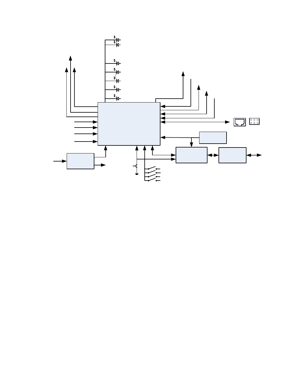
HDDA 1X9
CONTROLLER
BLOCK DIAGRAM
microController
System Clock
20MHz
CAN
Controller
CAN
Transceiver
+3.3V
Regulator
+12V
SLOT ID &
REAR BRD ID
+3.3V
RESET
CURRENT &
VOLTAGE
MONITORS
SPI
POWER
TEST
GRN
RED
RJ11 / 2X3 HEADER
DEBUG/PROGRAM
PORT
/CD
SD/HD
PLL_LOCK
/RSTO_4
OVERRIDE
YLW
SDA \ SCL
EQ_BYPASS/
MUTE
RATE0/1
RECLK_BYPASS\
MUTE
/RESET_1
EQ ON
RECLK ON
LOC/REM
CAN
BUS
EQ BYPASS
RE-CLK BYPASS
LOCKED
GRN
GRN
FRONT EDGE DIP SWITCH
SD/HD__SLEW
/FAULT
YLW
YLW
SD/AUTO
The PIC32 microcontroller, PIC32MX340F256H, was chosen based on cost and
familiarity of the engineering staff with this device. In order to be able to communicate
over the CAN bus in the openGear frame a CAN Controller IC, MCP2515 in conjunction
with a CAN bus transceiver, SN65HVD233D, is used. The CAN Controller is controlled by
the PIC32 using the SPI2 port of the PIC.
There are two Debug / Program ports in parallel with each other. One is a RJ11
connector that is positioned at the front edge of the board and used during the board
prototype phase. The other connector, a 2X3 header, will remain on the board in
production and has the same functions as the RJ11.
There is one regulated voltage on this module, +3.3V, which is regulated with a switching
supply, U23. The +3.3V is used to power the input current sense circuit, LMP8601 and all
the other active components. use +3.3V
The regulator section has one set of resistors, R53 and R54, for the positive supply which
are used to measure the current used by the positive supply. U11, LMP8601, is used to
measure the voltage across the current sense resistors, R53 and R54. LMP8601 is made
for this type of application and can handle the high common mode voltage that the
current sense voltage is riding on
A 20MHz system clock is generated for the PIC and the CAN Controller from a crystal
oscillator using two inverters in U16. Using a single external clock source makes the start
up of the board straight forward.