Gpio – Sensoray 2453 User Manual
Page 8
•
Configuration button;
•
LED indicators: green (top) – power, red (bottom) – special function;
•
Power (5 V DC, + on center).
GPIO
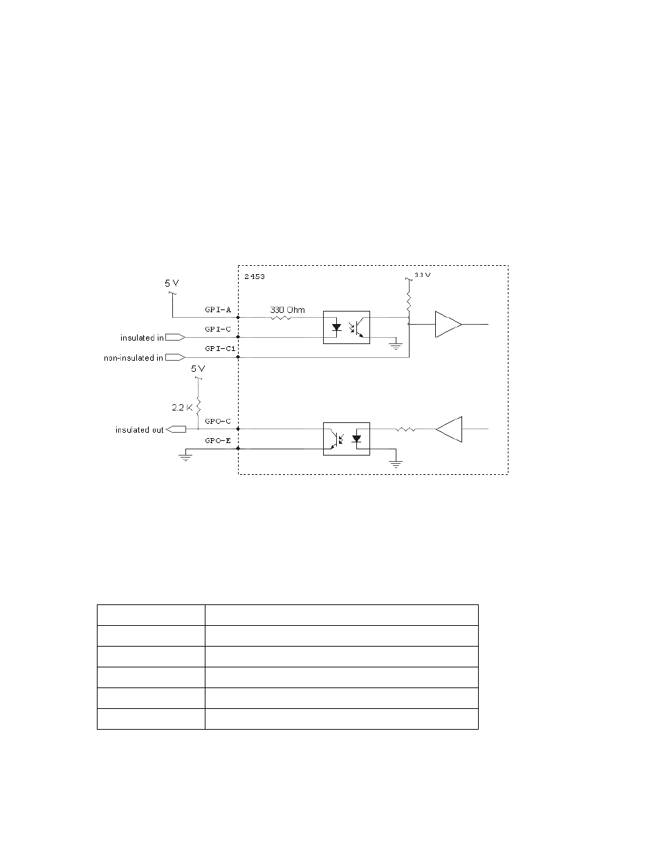
Model 2453 provides one general purpose input that could be either optically insulated
or galvanically coupled, and one general purpose optically insulated output. The
simplified schematic of the GPIO is shown on Fig.1.
Figure 1. Example of GPIO connections.
An example of connecting 2453's GPIO is shown on Fig.1. The optoisolators are Avago
ACPL-217. Please refer to the manufacturer's documentation for complete electrical
specifications.
Table 2. GPIO terminal block pinout (left to right).
1
GPI-C1
2
Ground
3
GPI-A
4
GPI-C
5
GPO-C
6
GPO-E
8
See also other documents in the category Sensoray Hardware:
- 2226 (15 pages)
- 2253 (19 pages)
- 616 (8 pages)
- 516 AVStream DirectShow (10 pages)
- 2246 (42 pages)
- 2246 (50 pages)
- 2255 (33 pages)
- 614 (17 pages)
- 611 (7 pages)
- 314 (14 pages)
- 614 Caption Overlay (18 pages)
- 311 (9 pages)
- 314 Quick Start (14 pages)
- 1012 (12 pages)
- 810 Quick Start (7 pages)
- 953-ET (17 pages)
- 911 (17 pages)
- 812 (16 pages)
- 810 (15 pages)
- 615 (8 pages)
- 615 (15 pages)
- 711 (36 pages)
- 609 (17 pages)
- 817 (11 pages)
- 817 (18 pages)
- 2411 (11 pages)
- 2250 (6 pages)
- 2263 (12 pages)
- 2263 (25 pages)
- 2480 (10 pages)
- 819 (11 pages)
- 516 (8 pages)
- 3011S (29 pages)
- 2444 (19 pages)
- 7429 (48 pages)
- 718 (22 pages)
- 518 (57 pages)
- 526 (29 pages)
- 526 (7 pages)
- 826 (76 pages)
- 2426 (17 pages)
- 721 (13 pages)
- 2410 (9 pages)
- 2600 (80 pages)