Channel status indicators: d1 ~ d4, Gpio status indicators: d5 ~ d8, Power-ok indicators: d11 ~ d15 – Sensoray 911 User Manual
Page 15
LED
Channel Status Indicators: D1 ~ D4
The LED D1, D2, D3, and D4 can be used for indicating the channel status.
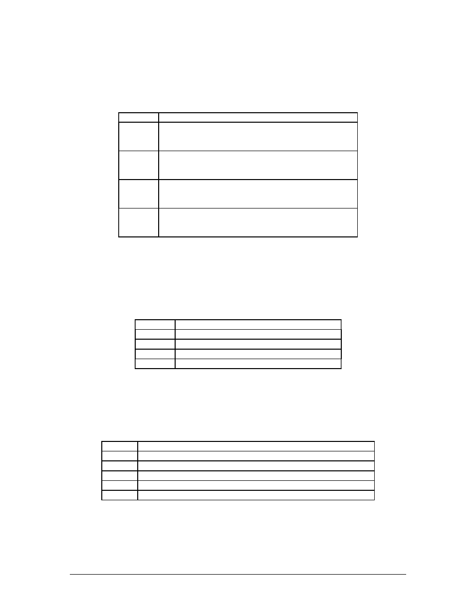
LED
Signal
D1
Status for Channel-1, the driving signal is connected to
the Channel-1 capturing chipset SAA713xHL’s GPIO15.
A logic low turns the LED on, and a high turns it off
D2
Status for Channel-2, the driving signal is connected to
the Channel-2 capturing chipset SAA713xHL’s GPIO15.
A logic low turns the LED on, and a high turns it off
D3
Status for Channel-3, the driving signal is connected to
the Channel-3 capturing chipset SAA713xHL’s GPIO15.
A logic low turns the LED on, and a high turns it off
D4
Status for Channel-4, the driving signal is connected to
the Channel-4 capturing chipset SAA713xHL’s GPIO15.
A logic low turns the LED on, and a high turns it off
GPIO Status Indicators: D5 ~ D8:
The LED D5, D6, D7, & D8 are used for indicating the status of the digital input/output
signals (pins), labeled as GPIO1 ~ GPIO4 on the board, and directly connected to the
J3. A logic 0 (low) turns the LED on and a logic 1 (high) turns it off.
LED
Signal
D5
Status of GPIO1 (associated with Channel-1)
D6
Status of GPIO2 (associated with Channel-2)
D7
Status of GPIO3 (associated with Channel-3)
D8
Status of GPIO4 (associated with Channel-4)
Power-OK indicators: D11 ~ D15
The LED D11, D12, D13, D14, and D15 are used for indicating on-board Power-OK
status.
LED
Signal
D15
3.3V Power-OK Status
D14
1.8V Power-OK Status
D13
1.5V Power-OK Status
D12
Power-OK Status for 1
st
PLX PEX8112 (PCI-Express to PCI Bridge)
D11
Power-OK Status for 2
nd
PLX PEX8112 (PCI-Express to PCI Bridge)
15