Dip switches, Digital i/o configuration dip switch: sw1, Manufacturing dip switch: sw2 – Sensoray 911 User Manual
Page 14: Stack-up/stack-down control dip switch: sw3
DIP Switches
Digital I/O Configuration DIP Switch: SW1
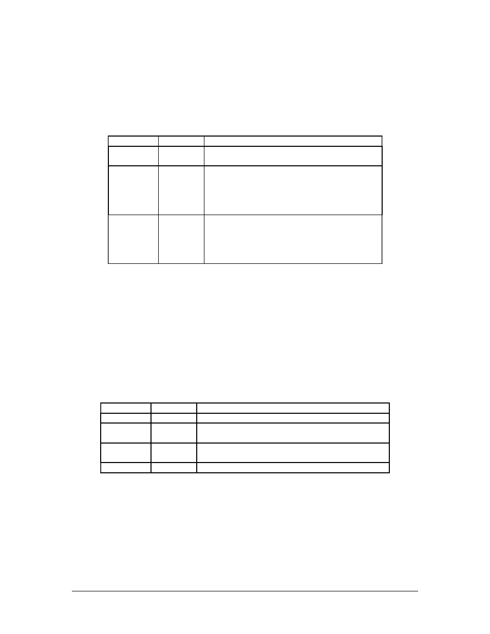
The DIP switch, SW1, is used for configuring Digital I/O routings. Refer to the table
below for the routing details:
SW1-1
SW1-2
Description
OFF
OFF
Disconnect all Digital Inputs/Outputs from/to
the Connector J1 and J3
ON
ON
Connect all four GPIO[4:1] signals from the
PEX8112 (PCI-Express-to-PCI Bridge) to the
Connector J1 and J3;
Configure the GPIO[4:1] as Digital Inputs or
Outputs, using software
ON
OFF
Connect all 4-channel GPIO signals from four
SAA713xHL chipset’s GPIO0 to the Connector
J1 and J3;
Configure the four GPIO0 signals as Digital
Inputs or Outputs, using software
Manufacturing DIP Switch: SW2
The DIP switch, SW2, is for Sensoray manufacturing only. Therefore, it is not described
in this manual.
Stack-Up/Stack-Down Control DIP Switch: SW3
The DIP switch, SW3, is used for PCIe/104 Stack-Up/Stack-Down Control/Configuring.
Refer to the table below for the configuring details:
SW3-1
SW#-2
Description
OFF
OFF
Stack-Up/Stack-Down Control by CPU board
ON
OFF
Stack-Up fixed (Just in case – CPU board has no
Stack-Up/Stack-Down Control signal provided)
ON
ON
Stack-Down fixed (Just in case – CPU board has no
Stack-Up/Stack-Down Control signal provided)
ON
OFF
Not Valid
14