Leds, Power-ok indicators: d13 ~ d18, Fpga status indicators: d25 ~ d27 – Sensoray 2226 User Manual
Page 13
13
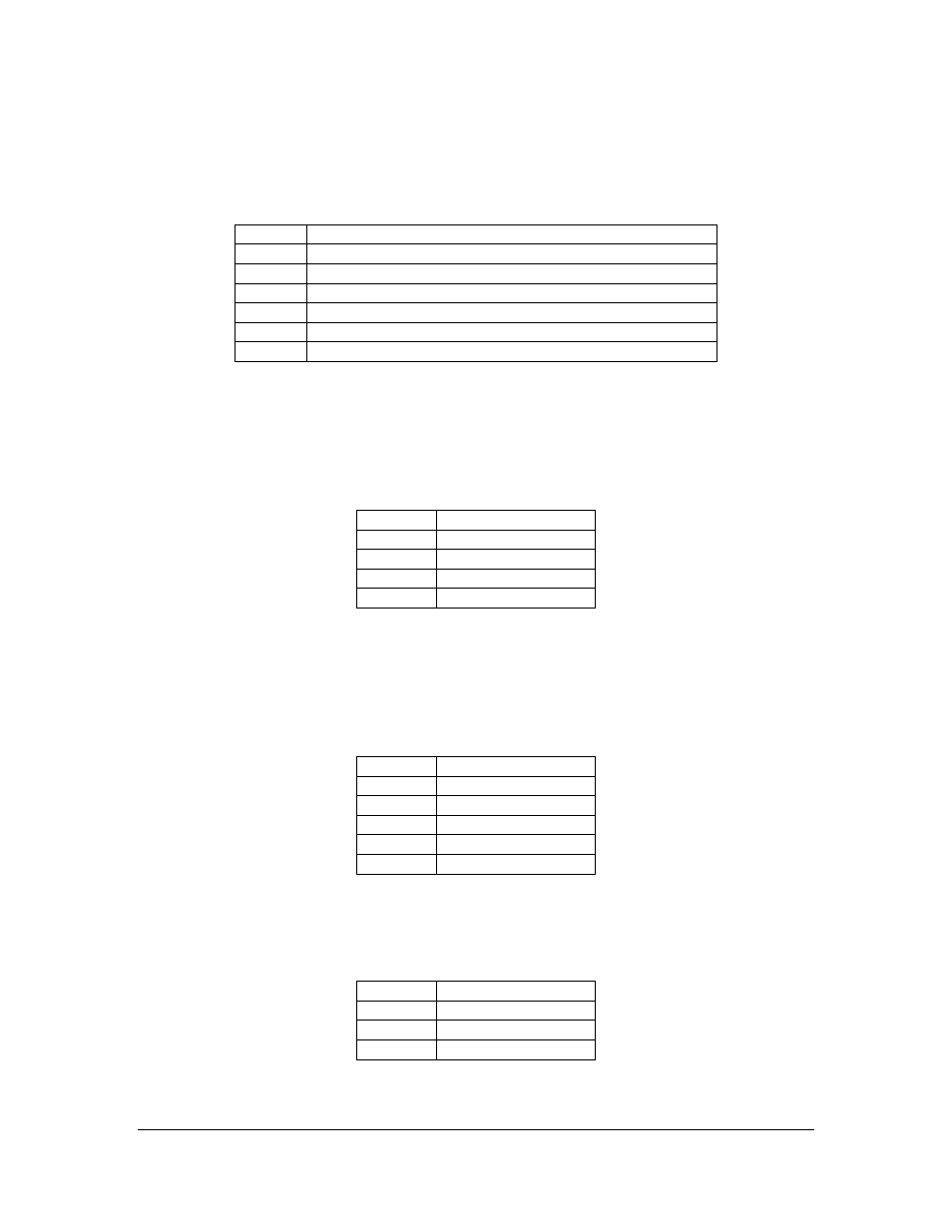
LEDs
Power-OK Indicators: D13 ~ D18
The LED D13 to D18 are used for indicating on-board Power-OK status.
LED
Signal
D13
+5V Power-OK Status
D14
+3.3V Power-OK Status
D15
+1.2V Power-OK Status
D16
+2.5V Power-OK Status
D17
+1.8V Power-OK Status
D18
All On-board +3.3V, +2.5V, and +1.8V Power-OK Status
USB General Purpose or Status Indicators: D21 ~ D24
The LED D21, D22, D23, and D24 are connected to the on-board USB device controller’s
pin PC0, PC1, PC2, and PA0, respectively. Therefore, they can be used as general
purpose indicators or status indicators, and are controllable via EZ-USB FX2 program.
Note that a logic 0 (low) turns the LED on and a logic 1 (high) turns the LED off.
LED
Signal
D21
FX2_PC0
D22
FX2_PC1
D23
FX2_PC2
D24
FX2_PA0
FPGA General Purpose Indicators: D1, D2, and D30 ~ D32
The LED D1, D2, and D30 to D32 are connected to the dedicated on-board FPGA’s I/O
pins. They can be used as general purpose indicators and are software controllable via
internal FPGA register. Note that a logic 0 (low) turns the LED on and a logic 1 (high)
turns the LED off.
LED
Signal
D1
EP3C16_LED1
D2
EP3C16_LED0
D30
EP3C16_GPO0
D31
EP3C16_GPO1
D32
EP3C16_GPO2
FPGA Status Indicators: D25 ~ D27
The LED D25, D26, and D27 are used for indicating the on-board FPGA’s status. Note
that a status signal logic 0 (low) turns the LED on and a logic 1 (high) turns the LED off.
LED
Signal
D30
EP3C16_STATUS8
D31
EP3C16_STATUS9
D32
EP3C16_STATUS10