Sensoray 2226 User Manual
Page 11
11
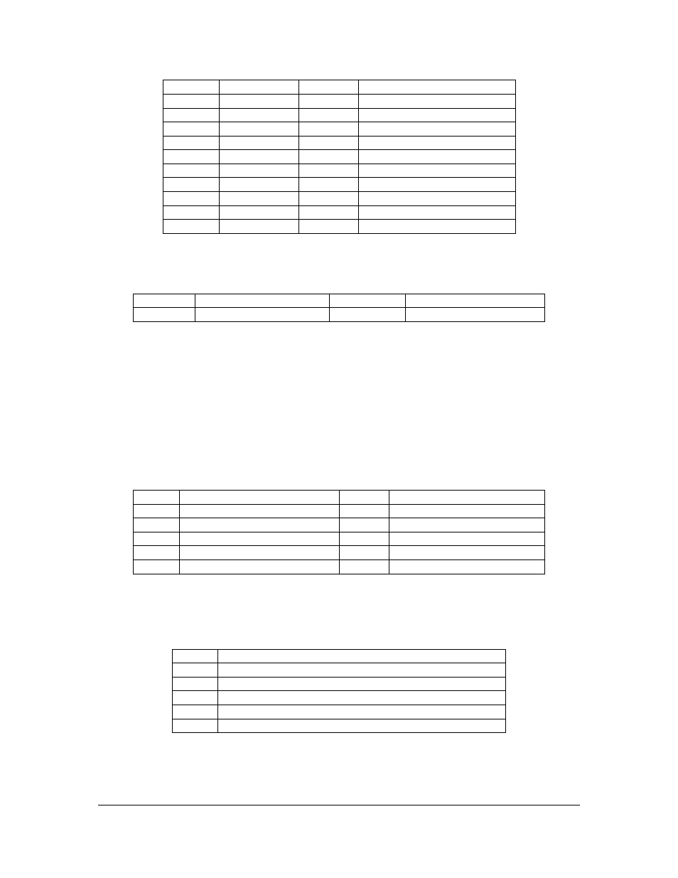
Pin
Signal
Pin
Signal
1
Ground
2
S-Video Input-0 -- Y
3
Ground
4
S-Video Input-0 -- C
5
Ground
6
Composite Video Input-0
7
Ground
8
S-Video Input-1 -- Y
9
Ground
10
S-Video Input-1 -- C
11
Ground
12
Composite Video Input-1
13
Ground
14
NC (No Connection)
15
Ground
16
Composite Video Output
17
Ground
18
S-Video Output -- Y
19
Ground
20
S-Video Output -- C
SD Composite Video Input, BNC: J8
It is used for main SD (Standard Definition) Composite video input.
Pin
Signal
Pin
Signal
Inner
SDI Video Signal
Outer/Ring
Shield, Analog Ground
SAM-ICE Connector: J9
It is for internal manufacturing/debugging only. Therefore, it is not described in this
manual.
JTAG Connector: J10
It is for internal board debugging only. Therefore, it is not described in this manual.
Audio Output Breakout Connector, 10-Pin: J11
It breaks-out all the Audio Outputs.
Pin
Signal
Pin
Signal
1
Headphone Output -- Left
2
Headphone Output -- Right
3
Mono Line Output -- LO+
4
Mono Line Output -- LO-
5
Stereo Line Output -- Left+
6
Stereo Line Output -- Left-
7
Stereo Line Output -- Right+
8
Stereo Line Output -- Right-
9
Analog Ground
10
Analog Ground
USB 2.0 HS (High Speed) Connector, 5-Pin Header: J12
It is Main Interface to the Host PC or CPU Module, via this USB 2.0 HS (High Speed)
connector.
Pin
Signal
1
Passive, connected to a 0.1uF decoupling cap to ground
2
Data-
3
Data+
4
Ground
5
Shield