Connector pin/signal definitions – Sensoray 2226 User Manual
Page 10
10
Connector Pin/Signal Definitions
Internal Board Test Connector: J1
It is used for internal/manufacturing test only. Therefore, it is not described in this
manual.
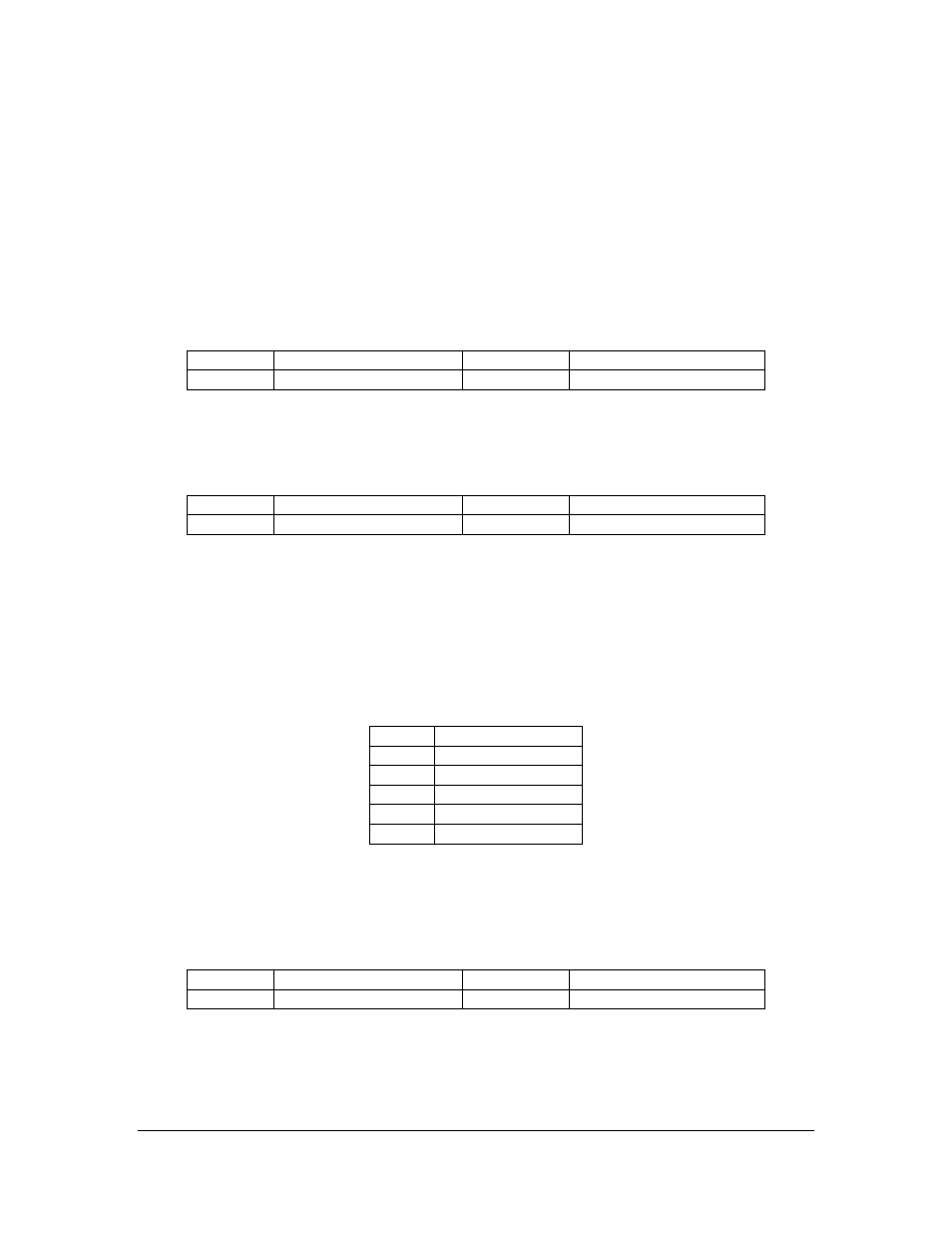
SDI Video Output-1, BNC: J2
It is main HD/SD (High Definition / Standard Definition) video output using SDI (Serial
Digital Interface). Model 2226 provides two SDI outputs for the multiple monitoring
need. The SDI video output-1 duplicates the SDI video output-0.
Pin
Signal
Pin
Signal
Inner
SDI Video Signal
Outer/Ring
Shield, Analog Ground
SDI Video Input, BNC: J3
It is main HD/SD (High Definition / Standard Definition) video input using SDI (Serial
Digital Interface).
Pin
Signal
Pin
Signal
Inner
SDI Video Signal
Outer/Ring
Shield, Analog Ground
A/V Break-in and Break-out Connector: J4
It is used for building Sensoray Model 2420, a streaming server product, only.
Therefore, it is not described in this manual.
USB 2.0 HS (High Speed) Connector, 5-Pin Header: J5
It is used for connecting the high speed USB 2.0 interface of the ARM9 processor on the
Model 2226, off the board.
Pin
Signal
1
VBUS +5V
2
Data-
3
Data+
4
Ground
5
Shield
SDI Video Output-0, BNC: J6
It is main HD/SD (High Definition or Standard Definition) video output using SDI (Serial
Digital Interface). Model 2226 provides two SDI outputs for the multiple monitoring
need. The SDI video output-0 duplicates the SDI video output-1.
Pin
Signal
Pin
Signal
Inner
SDI Video Signal
Outer/Ring
Shield, Analog Ground
SD Video Input and Output Connector, 20-Pin: J7
This connector breaks-in and breaks-out all the SD (Standard Definition) video inputs
and outputs, including Composite Video In/Out and S-Video In/Out.