0 accessories, Nl5000 serial interface cable – RF Neulink NL5000 Rev B0 User Manual
Page 10
NL5000 User Manual Rev B0
9
modem’s packet detection system, not the fact that a signal may actually be
present. To determine the presence of a carrier, one can monitor the state of the
Carrier Detect output.
RED TX LED This indicator is illuminated when the modem is transmitting.
3.3
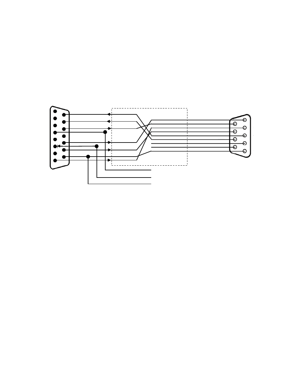
NL5000 - DB 15 to DB 9 Interface Cable
D1
1
2
3
4
5
6
7
8
9
1
2
3
4
11
10
5
6
7
8
9
12
13
14
15
DB 15 Male
DB 9 Female
Tx Data
Rx Data
CTS
DSR
DCD
RTS
GND
+12 VDC
A/B Ch.
DCD
DSR
Rx Data
RTS
Tx Data
CTS
GND
RED
BLK
WHT
NL5000 Serial Interface Cable
D1
1
2
3
4
5
6
7
8
9
1
2
3
4
11
10
5
6
7
8
9
12
13
14
15
DB 15 Male
DB 9 Female
Tx Data
Rx Data
CTS
DSR
DCD
RTS
GND
+12 VDC
A/B Ch.
DCD
DSR
Rx Data
RTS
Tx Data
CTS
GND
RED
BLK
WHT
NL5000 Serial Interface Cable
The above interface cable facilitates the connection of standard RS-232 signals to
a typical 9 pin “D” type female connector. This cable additionally accommodates
the connection of the +12 VDC, Ground and the A/B power or channel selector to
the 15 pin “D” type female connector on the NL5000 front panel. As shown, D1 is
placed in series between pin 6 and the + 12 VDC supply voltage and provides
reverse polarity protection.
4.0 ACCESSORIES
Note: Configuration Software kits are for use by authorized
service/maintenance personnel only.
The Configuration Software Kit for NL5000 (via compatible computer) is model
NL5000P-PCKT. It includes:
1. Configuration Software disk, CD (qty 1).
2. A Configuration Software/Power cable with a DB-15 Male connector on one
end for connection to the NL5000 modem and a cable to a DB-9 Female
connector for connection to the host computer and two wires, one red (positive)
and one black (negative) for connections to a power supply.
Factory Configuration of channels and features is also optional. Contact the factory
for details.