Electrical wiring diagram, Electronic control board, Sle 40 - sle 80 – REMKO SLE 40 User Manual
Page 13
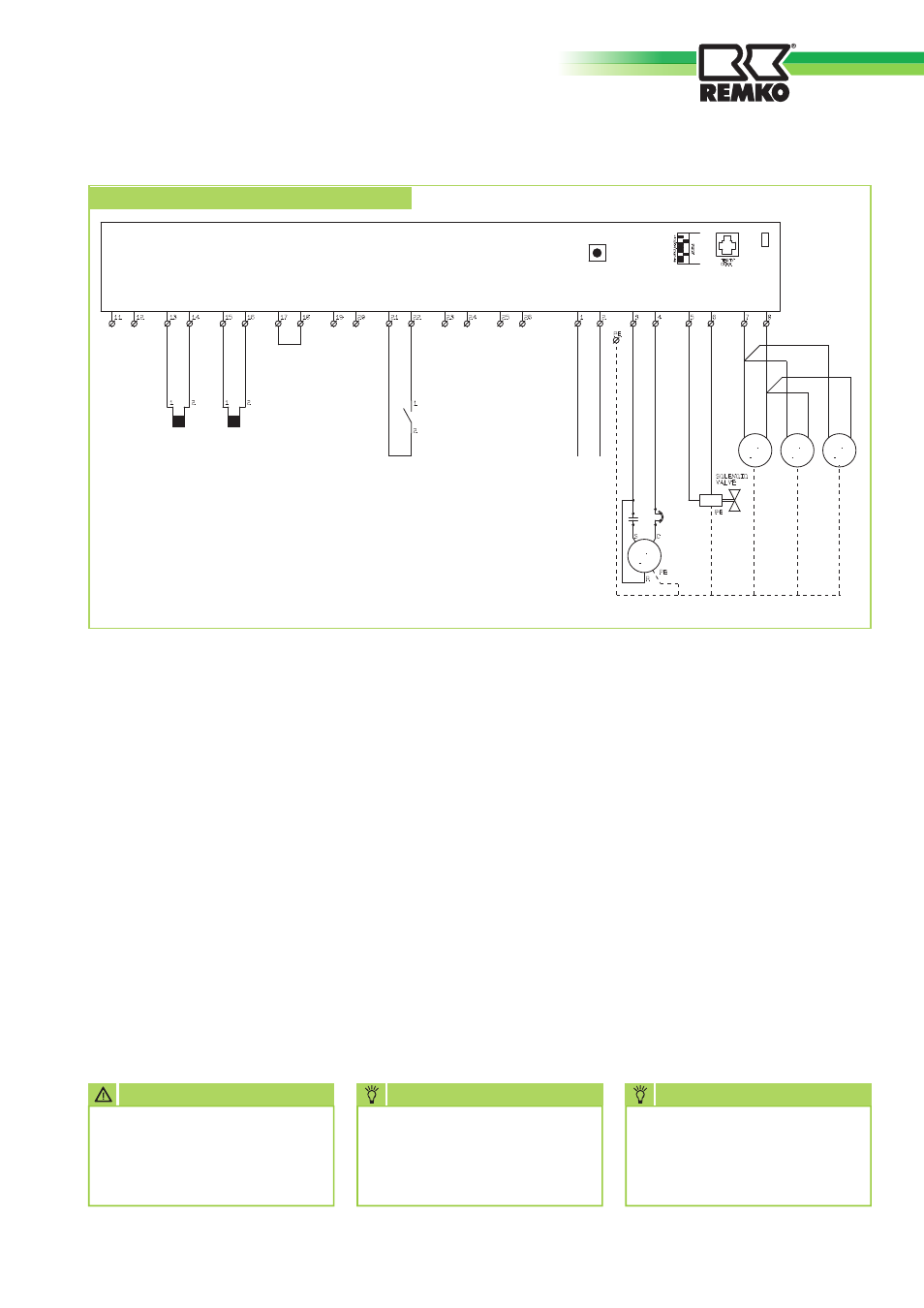
Legend:
HYG = Hygrostat
M 1 = Compressor
M 2 = Fan motor 1
M 3 = Fan motor 2
M 4 = Fan motor 3
Y 1 = Solenoid valve
R3.1 = Condenser sensor
R3.2 = Evaporator sensor
Electrical wiring diagram
R3.1
R3.2
HYG
L1 N
230V
50 Hz
M 1
M
1~
M
1~
M 2
Y 1
Test
M
1~
M
1~
M 4
M 3
AMB.
NTC
COND.
NTC
EVAP.
NTC
PRES.
THA
WAT.
SENS
HYG
TH.
STAT
FAN
MAINS
FAN
COMPR.
VALVE
HEAT
Fan motors:
SLE 40 = Motor M2
SLE 60 = Motor M2 and M3
SLE 80 = Motor M2, M3 and M4
Constant ventilation:
If constant air circulation is re-
quired, i.e. independent of de-
humidification, a jumper can be
connected between terminals 25
and 26
.
The fan or fans then operate with-
out any control and monitoring in
a continuous mode.
External hygrostat:
Recommended for frequent hu-
midity variation is the installation
of an external hygrostat which is
available as an accessory.
Disconnect the integrated hygro-
hygro-
stat at terminals 21 and 22.
Install the external hygrostat at a
suitable location in the room to
be dehumidified and connect to
terminals 21 and 22.
The output voltage on terminals
21 and 22
is 12V.
NOTE
Only authorised special-
ists may install and carry out
maintenance work on the
units!
Electronic control board
NOTE
A disconnector switch should
be installed in the supply con-
nection at a suitable and easily
accessible location.
ATTENTION
Prior to carrying out mainte-
nance or repairs, the unit must
always be disconnected from
the supply.
We reserve the right to make dimensional and design changes in the interest of technical advances.
SLE 40 - SLE 80
13