M~ m, Electrical connection diagram – REMKO ETF 400 User Manual
Page 15
+
+
M
~
M
~
L1 N
PE
h
aC
Kompressor
S2
H1
H2
S3
M1
M2
Y1
P1
S1
K1
230V 50Hz
2
3
1
H
C
R
S
C
7
6
5
2
8
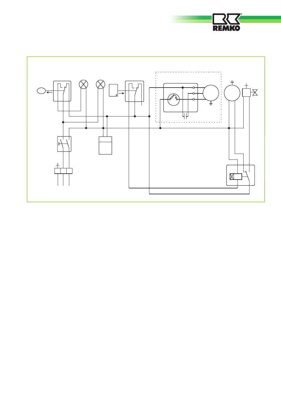
Electrical connection diagram
H1
=
Control lamp (yellow = container full)
H2
=
Control lamp (green = in operation)
K1
=
Time relay (t = 30 min.)
M1
=
Compressor motor
M2
=
Fan motor
P1
=
Operating hours counter
S1
=
Operating switch
S2
=
Microswitch (float)
S3
=
Defrost - thermostat
Y1
=
Defrost - solenoid valve
We reserve the right to modify the dimensions and constructional design as part of the ongoing technical development process.
15
This manual is related to the following products:
See also other documents in the category REMKO Radiators:
- PWL H (24 pages)
- CLK 150 (20 pages)
- ELT 2-1 (12 pages)
- CLK 170-RV (24 pages)
- DZH 90-2 (20 pages)
- ELT 18 S V.2 (12 pages)
- ELT 9 (12 pages)
- ELT 9-6 (12 pages)
- EST (8 pages)
- PGM 60 (16 pages)
- PGM 12 (12 pages)
- HTL 400 (20 pages)
- PGT 100 (20 pages)
- ATR-3 (16 pages)
- ATR-4 (16 pages)
- SLV11-88-2 (16 pages)
- PWW Series (36 pages)
- GTF-5 (8 pages)
- VRS Series (36 pages)
- GSG-4 (8 pages)
- GPM 75 (44 pages)
- ATR-2 (8 pages)
- ASF 100 (16 pages)
- ETF 460 (20 pages)
- ETF 320 (20 pages)
- WKL 30 INOX (24 pages)
- SLN 80 (20 pages)
- RBW 300 PV-S (48 pages)
- HTS 260 CAMURA (76 pages)
- WKF 180 Duo S-line (64 pages)
- WKF-compact S-Line (96 pages)
- AMT 15 (16 pages)
- AMT 25 (16 pages)
- ETF 220 (16 pages)
- TX 3000 (8 pages)
- PG 50 (16 pages)
- TX 9000 (8 pages)
- CLK 20 (20 pages)
- AT 25 (16 pages)
- DZ 18 HD (16 pages)
- HTK 160 (20 pages)
- PG 12E (16 pages)
- PWL (24 pages)
- PWW 5000 (12 pages)