Wiring diagram, Hr kl, Srt hw2 hw1 nk tb m – REMKO ELT 3-2 User Manual
Page 10
10
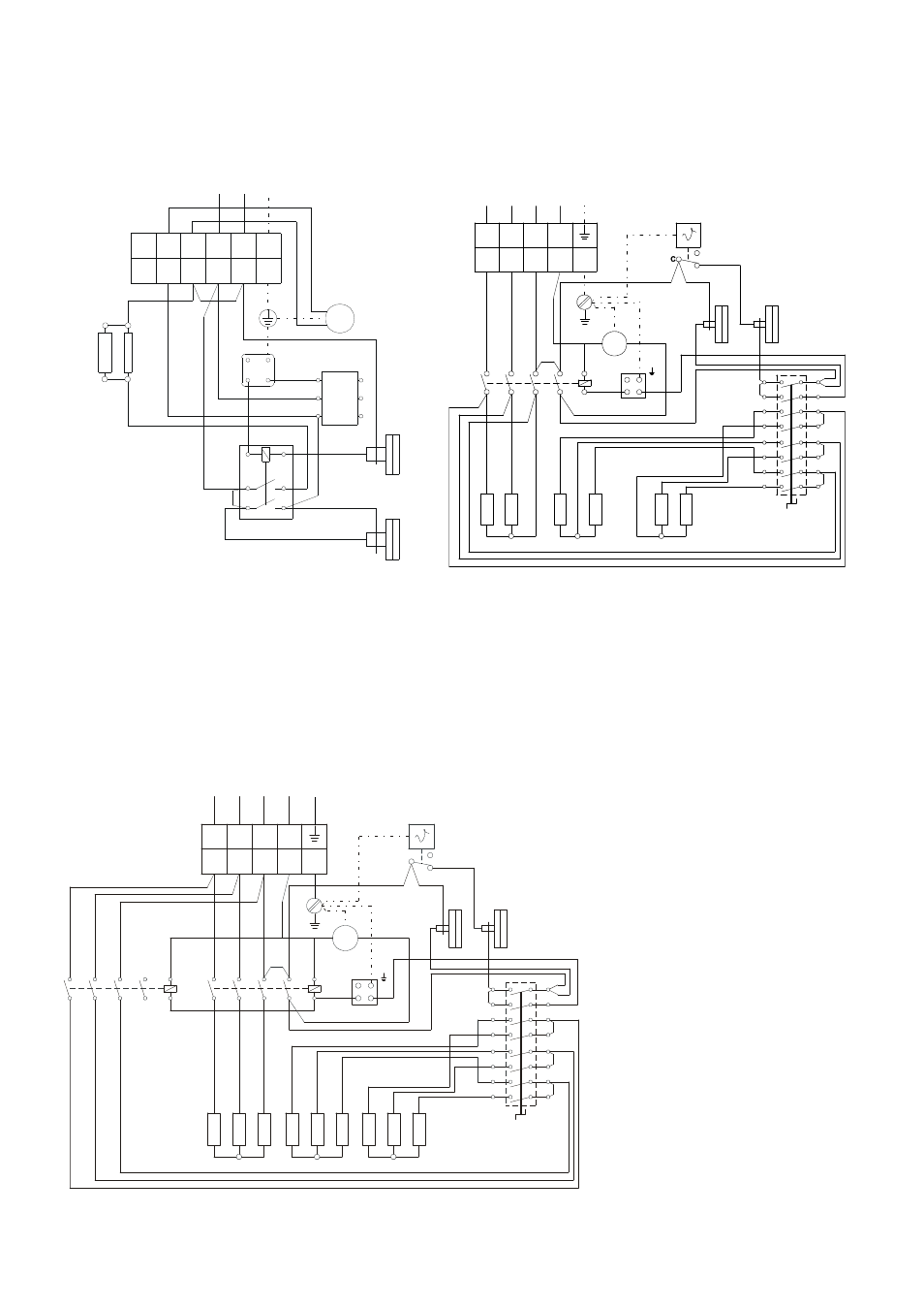
Wiring Diagram
400 3/N ~ 50Hz
ELT 3-2
ELT 10-6
ELT 18-9
HR = contactor
KL
=
terminal strip
S
=
operating switch
HW = heating element
M
=
fanmotor
STB =
temperature limiter (with sensor)
K1 = contactor 1
NK =
recool thermostat
TB
=
temperature limiter
K2 = contactor 2
RT =
thermostat socket
We reserve the right to make modifications in dimensions and construction in the interests of technical progress.
4 L1
PE
6
5
4
3
N
2
1
6
5
PE
N
L1
1A
2A
3A
4B
5B
6B
13
14
23
24
a
b
HR
KL
2
3
1
S
RT
HW2
HW1
NK
TB
M
230 V / 1~, N, PE / 50 Hz
400 V / 3~, N, PE / 50 Hz
400 V / 3~, N, PE / 50 Hz
2
1
3
4
5
6
13
14
A2
A1
2
3
RT
NK
TB
1
2
STB
K1
S
HW
M
V3
V5
V1
H
M
L1 L2 L3
N PE
KL
L2
V4
L3
L1
V2
V6
L2 L3
1 2 3 4 5
N
L1
2
1
3
4
5
6
13
14
A2
A1
C
1
2
2
1
3
4
5
6
13
14
A2
A1
2
3
L2
V4
L3
L1
V2
V6
V3
M
H
V5
V1
L2 L3
1 2 3 4 5
N
L1 L2 L3
N PE
M
L1
NK
TB
RT
STB
K1
K2
HW
S
KL