Electrical connection – REMKO RKS 327 H User Manual
Page 20
20
G
Prior to performing any work on the unit, it must be
unplugged from the power supply and secured
against being inadvertently switched on!
Electrical Connection
For all units, the power supply must be installed on the
indoor units. The system’s fuse protection must be in
line with the technical requirements and the local condi-
tions.
Local guidelines for operation as well as the require-
ments established by local energy supply companies
must be observed for setup and initial operation.
Connecting the indoor unit
Proceed as follows to connect the lines:
1. Open the cover of the connection area of the indoor
unit.
2. Connect the power connection line of the indoor unit
to the power supply.
3. Close the customer-installed connection lines as de-
scribed below on the connection terminals of the in-
door unit.
4. Place the customer-installed connection lines to the
outdoor part.
Instructions for electrical connection
Inside the indoor units for all air-conditioning units, there
are connection terminals for the power connection and
the customer-supplied connection line.
The power connection line is already permanently wired
in the indoor unit up all air-conditioners. If the existing
power connection line is not long enough, replace it
keeping in mind the required cross-sections and termi-
nal connections.
For the RKS 350 H units, the sensor line supplied with
the unit must also be laid. If the distance to be covered
with this line is more than 10 m, the line must be length-
ened by the customer!
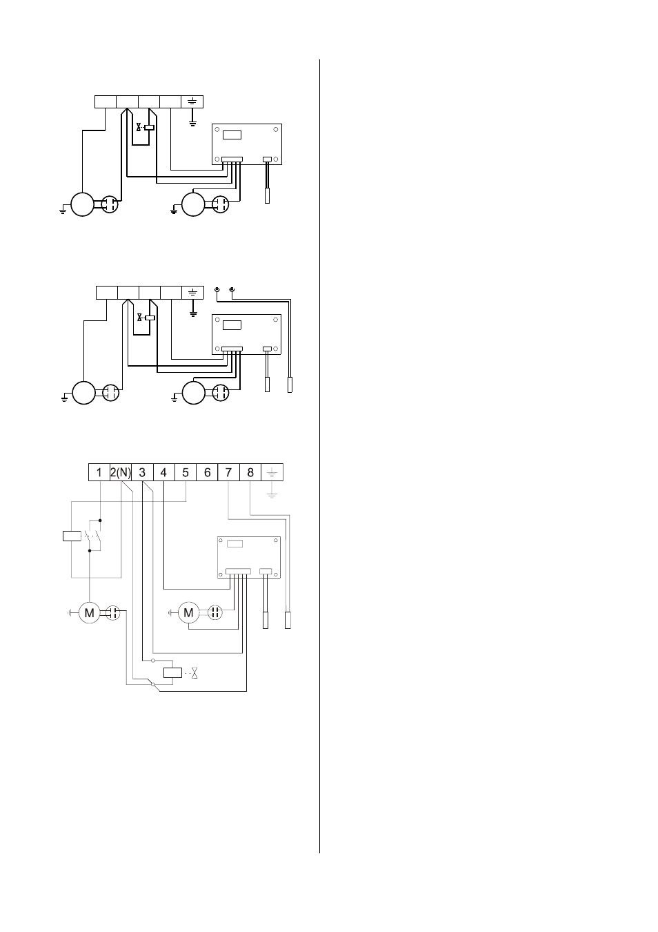
Electrical wiring diagram RKS 327 / 335 H AT
Condenser fan
1 2(N) 3
4
Compressor
Winter regulation mechanism
Sens
or
flui
d l
in
e
Condenser
Condenser
Reverse
valve
M
M
1 2(N) 3
4
Winter regulation mechanism
Condenser fan
Compressor
Sens
or
flui
d l
ine
Condenser
Condenser
Reverse
valve
M
M
Plug
Sens
or
fr
os
t pr
otec
tion
Electrical wiring diagram RKS 350 H AT
Electrical wiring diagram RKS 371 H AT
Condenser fan
Compressor
W
inter
r
egul
ati
on
m
e
chani
sm
Condenser
Reverse valve
C
ontac
tor
Condenser
Sens
or
f
lui
d l
ine
Sens
or
f
ros
t pr
otec
tion
Before proceeding with the connections, please read
the following instructions:
à
Electrical installations may only be performed by
authorised service personnel in accordance with the
relevant regulations.
à
An all-channel main switch must be installed by the
customer in the supply line close to the indoor unit;
we recommend using a main or repair switch.
à
Power for the outdoor part is supplied via the con-
nection line from the indoor unit.
à
The power supply’s cross-section is based on the
design specifications and the connection capacity of
the unit.
à
The connection lines to be installed by the customer
can be combined as follows:
RKS 327 H to RKS 350 H
A 3-wire and a 2-wire connection line or a 5-wire
connection line.
RKS 371 H
A 3-wire and a 6-wire connection line.
à
In some cases, we recommend separating the con-
trol line and the power supply line (L / N / PE) of the
outdoor part into two different lines with different
cross-sections for the units RKS 335 H to RKS 371 H.