Nozzle, Pump rotor – Desa 110 User Manual
Page 13
13
099176
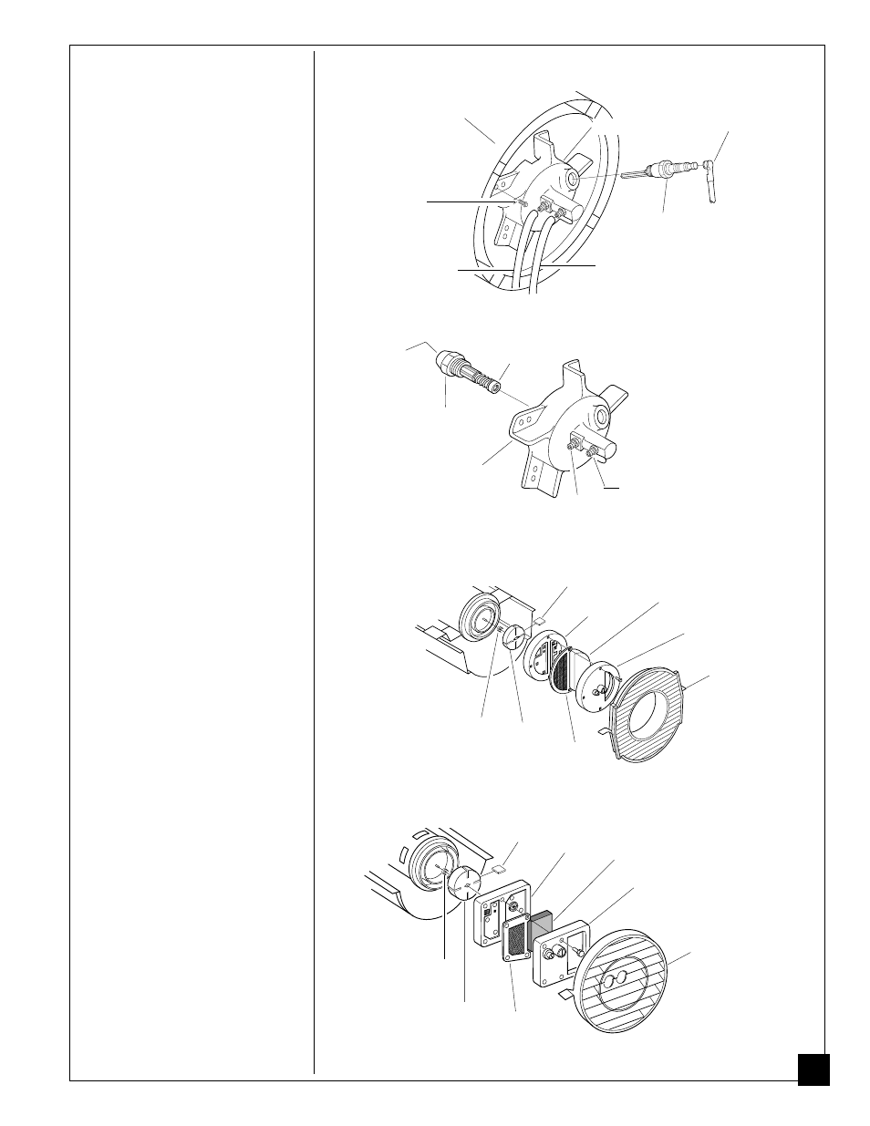
Nozzle
(70/100/110/150,000 BTU/Hr Models)
1. Remove upper shell (see page 10).
2. Remove fan (see page 10).
3. Remove fuel and air line hoses from
burner head.
4. Remove spark plug wire from spark
plug.
5. Remove spark plug from burner
head using 13/16" open-end wrench.
6. Remove three (3) screws using
5/16" nut-driver and remove burner
head from combustion chamber.
7. Place burner head into vise and
lightly tighten.
8. Carefully remove nozzle from
burner head using 5/8" socket
wrench (see Figure 26).
9. Blow compressed air through face
of nozzle. This will free any dirt in
nozzle area.
10.Inspect nozzle seal for damage.
11.Replace nozzle into burner head and
tighten firmly (80-110 inch-pounds).
12.Attach burner head to combustion
chamber.
13.Install spark plug in burner head.
14.Attach spark plug wire to spark
plug.
15.Attach fuel and airline hoses to
burner head.
16.Replace fan (see page 10).
17.Replace fan guard and upper shell.
Burner Head
Spark Plug
Wire
Spark
Plug
Combustion
Chamber
Screw
Fuel Line Hose
Air Line Hose
Figure 25 - Removing Burner Head, 70/100/110/150,000 BTU/Hr Models
Continued
Burner
Head
Nozzle
Nozzle
Face
Nozzle
Seal
Fuel Line
Fitting
Air Line
Fitting
Figure 26 - Removing Nozzle, 70/100/110/150,000 BTU/Hr Models
50 ROTOR
PFA/P 056
Pump
Plate
Blade
Air Intake
Filter
Filter End
Cover
Fan Guard
Rotor
Insert
Air Output
Filter
Figure 27 - Rotor Location, 35/50/55/70,000 BTU/Hr Models
100 ROTOR-Domestic
PFA/P 059A
Blade
Pump
Plate
Air Intake
Filter
Filter End
Cover
Insert
Rotor
Air Output
Filter
Figure 28 - Rotor Location, 100/110/150,000 BTU/Hr Models
Fan Guard
Pump Rotor
(Procedure if rotor is binding)
1. Remove upper shell (see page 10).
2. Remove filter end cover screws
using 5/16" nut-driver.
3. Remove filter end cover and air
filters.
4. Remove pump plate screws using
5/16" nut-driver.
5. Remove pump plate.
6. Remove rotor, insert, and blades.
7. Check for debris in pump. If debris
is found, blow out with compressed
air.
8. Install insert and rotor.
9. Check gap on rotor. Adjust to
.003"/.004" if needed (see Figure
29).
Note:
Rotate rotor one full turn to
insure the gap is .003"/.004" at tightest
position. Adjust if needed.