Desa 110 User Manual
Page 12
12
099176
11. Tighten spark plug with spark plug
mounting nut.
12. Release hex-body of spark plug from
vise.
13. Replace burner strap onto combustion
chamber.
14. Attach spark plug wire to spark plug.
15. Attach fuel and air line hoses to
nozzle assembly.
16. Replace fan (see page 10).
17. Replace fan guard and upper shell.
Spark Plug
(70/100/110/150,000 BTU/Hr Models)
1. Remove upper shell (see page 10).
2. Remove fan (see page 10).
3. Remove spark plug wire from spark
plug.
4. Remove spark plug from burner head
using 13/16" open-end wrench.
5. Clean and regap spark plug elec-
trodes as follows:
70/100,000 BTU/Hr
Models = .055" gap
110/150,000 BTU/Hr
Model = .075" gap
6. Install spark plug in burner head.
7. Attach spark plug wire to spark plug.
8. Replace fan (see page 10).
9. Replace fan guard and upper shell.
Nozzle
(35/50/55,000 BTU/Hr Models)
1. Remove upper shell (see page 10).
2. Remove fan (see page 10).
3. Remove fuel and air line hoses from
nozzle assembly.
4. Turn nozzle assembly 1/4 turn to left
and pull toward motor to remove.
5. Place plastic hex-body into vise and
lightly tighten.
6. Carefully remove nozzle from the
nozzle adapter using 5/8" socket
wrench.
7. Blow compressed air through face of
nozzle. This will free any dirt in
nozzle area.
8. Inspect nozzle seal for damage.
9. Replace nozzle into nozzle adapter
until nozzle seats. Tighten 1/3 turn
more using 5/8" socket wrench (40-
45 inch-pounds).
10. Attach nozzle assembly to burner
strap.
11. Attach fuel and airline hoses to
nozzle assembly.
12. Replace fan (see page 10).
13. Replace fan guard and upper shell.
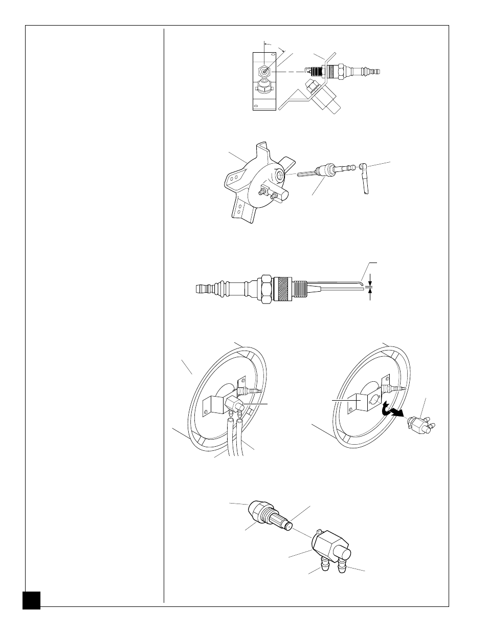
45
°
Figure 19 - Spark Plug Rotation, 35/50/55,000 BTU/Hr Models Only
Burner
Strap
Spark
Plug
Spark Plug
Wire
Burner
Head
Figure 20 - Spark Plug Removal, 70/100/110/150,000 BTU/Hr Models
Figure 21 - Spark Plug Gap, 70/100/110/150,000 BTU/Hr Models
Gap
Bend Here
to Adjust
Gap
Nozzle
Nozzle
Face
Nozzle
Adapter
Air Line
Fitting
Fuel Line
Fitting
Nozzle
Seal
Figure 24 - Nozzle and Nozzle Adapter, 35/50/55,000 BTU/Hr Models
Nozzle
Assembly
Fuel Line Hose
Nozzle
Assembly
Figure 22 - Removing Air and Fuel Line
Hoses, 35/50/55,000 BTU/Hr Models
Figure 23 - Removing Nozzle Assembly,
35/50/55,000 BTU/Hr Models
Burner
Strap
Combustion
Chamber
Air Line Hose