Quantum Composers System and Channel Modes User Manual
Page 2
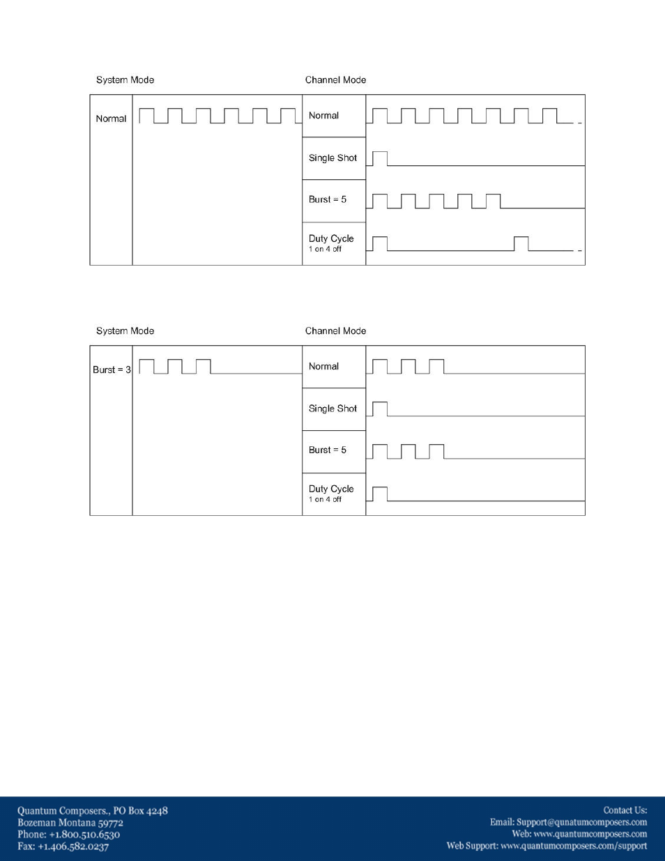
Figure 2 shows a pictorial representation of the system mode and its relationship to the channel modes. In this
figure the channel mode limits the output.
Figure 2
Figure 3 shows an example of where the system mode (Burst =3) limits the output as compared to Figure 2.
Figure 3
Notice that in figure 2, even though the channel burst mode is set to 5 only 3 pulses are output. A similar effect
is seen if the channel mode was set to duty-cycle.
The output will be generated off of the more restrictive of the two modes. If the system mode is set to
continuous and the channel mode is burst, only a burst of pulses will be generated, thus the output is limited by
the channel mode. If the system mode is set to burst and the channel mode is normal only a burst will be
generated but this time the output is limited by the system mode setting. While the output generated by the 2
examples above is the same (a burst of pulses) there are some minor differences.
In the first example where the system is set to continuous and the channel is set to burst the output set of
pulses will only occur once but the system run indicator will continue to flash. (Note: the system run indicator is a
flashing circle located in the upper left hand corner of the display) In this configuration, the channels can be re-
armed by pressing the function (FUNC) button followed by the RUN/STOP button. With the system being set to
continuous and the channel being the limiter, one channel could be left at normal and a second channel could be
set to burst or single shot. This type of two stage architecture allows for the generation of complex pulse outputs
that other pulse generators cannot achieve.