Aec control boxes, Control box wiring aec 200-2, 115 v ac/dc – Profax AEC 200 User Manual
Page 19: Elec. + gun, Aec 200-1, Aec 200-2
17
16
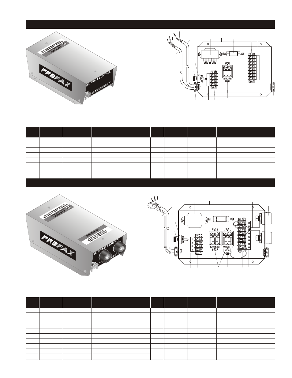
Contactor and power cable plugs are not provided with the AEC 200-1 Control Box, due to its compatibility with such a large number of power sources
which require different plugs. We suggest you contact your distributor for the proper plugs or we can supply them if we are provided with machine
model and serial number.
ELEC.
PART
NO.
COMP.
NO.
DESCRIPTION
1
8328A
Cover, top (not shown)
2
8329A
Base
3
6100
Fuse holder
4
F1
6101
Fuse 1¼ amp slo blo (not shown)
5
7026
Strain relief (2)
6
TS1
7008
Terminal strip 8 pole
7
8008
Decal, 8 pole terminal strip
8
TS2
7004
Terminal strip 4 pole
ELEC.
PART
NO.
COMP.
NO.
DESCRIPTION
1
8328A
Cover, top (not shown)
2
8330A
Base
3
6100
Fuse holder
4
F1
6101
Fuse 1¼ amp slo blo (not shown)
5
7026
Strain relief (2)
6
TS1
7008
Terminal strip 8 pole
7
8008
Decal, 8 pole terminal strip
8
TS2
7004
Terminal strip 4 pole
9
8004
Decal, 4 pole terminal strip
10
SR1
6314
Bridge rectifier
AEC CONTROL BOXES
AEC 200-1
ELEC.
PART
NO.
COMP.
NO.
DESCRIPTION
9
8004
Decal, 4 pole terminal strip
10
SR1
6314
Bridge rectifier
11
CR1
6271
Relay, 3 PDT-24VAC (2)
12
T1
6416
Transformer, step down
13
R1
6010
Resistor, 10 ohm 25 watt
14
6182
Cable, 5’ 18/2
15
6183
Cable, 5’ 18/3
AEC 200-2
*N/S-Not Shown
CONTROL BOX WIRING AEC 200-2
F1
11
5
V
A
C
2
4
V
GRD
CR1
8
3
7
4
1
A
5
B
CR1
B CR
1
SR
1
CR1
CR3
AC
REED
R1
TRIGGER
M
CR
2
CR3
D1
CR2
REED
CR1
CR
3
9
9
6
4
7
A
9
6
TS1
1
2
3
4
TS2
22
21
20
16
15
14
13
23
WORK -
ELEC. +
GUN
SPOOL GUN
AC
(JOG optional)
CONTROL BOX WIRING AEC 200-3A
CONTROL BOX WIRING
AEC 200-C
Contactor and power cable plugs are not provided with the PXAEC 200-2 Control Box, due to its compatibility with such a large number of power
sources which require different plugs. We suggest you contact your distributor for the proper plugs or we can supply them if we are provided with
machine model and serial number.
ELEC.
PART
NO.
COMP.
NO.
DESCRIPTION
11
CR1,CR3
6271
Relay, 3 PDT-24VAC (2)
12
T1
6416
Transformer, step down
13
R1
6010
Resistor, 10 ohm 25 watt
14
CR2
6022
Current relay (w/reed switch)
15
08106
Dinse panel mount (2)
16
6183
Cable, 5’ 18/3
17
6023
Reed switch only
18
6255
Sensor lead
19
D1
6272
Relay diode assembly
(8 amp 600 volt)
GUN
W
TB4
110V DC RELAY
K1
C1
C2
23
RED
13
YEL
14
BLU
M
15
GRN
GUN RHEOSTAT
GUN MOTOR
GUN
TRIGGER
16
BLK
20
21
22
FLUX COLLECTOR
BLUE/WHITE
BROWN/WHITE
BLACK
F2
WELDER
(SENSOR LEAD)
WELDER
POS.
RED/BLACK
4 3 2 1
PROFAX INC.
MADE IN U.S.A.
WIRE FEEDER
CONTROL BOARD
6000B
ORG PUR
TB3
TB2
R6
PURPLE
GRAY
YELLOW/WHITE
ORANGE/BLACK
4
BLACK/WHITE
CONTACTOR
YELLOW
3
W
2 1
1
2
3
4
R5
WHITE
GRN
120V
AC/DC
F1
R11
22
21
20
16
15
14
13
23
6
7
8
9
10
1
2
3
4
5
13
2
12
15
14
11
7
6
8
9
10
5
3
5
5
17
7
15
6
19
14
11
13
8
10
3
16
2
9
18
12
F1
115 V
AC/DC
CR1
SR
1
AC
VR1
9
6
ELEC. +
GUN
AC
CAUTION-Due to the design of the magnetic blow-out, welding current polarity
must be properly connected or permanent damage to contacts may result.
Consult wiring and cable connection drawing below in fig. 1A.
R1
W
VR2