Caution, 115 v ac/dc, Fig. 1a – Profax AEC 200-C User Manual
Page 3
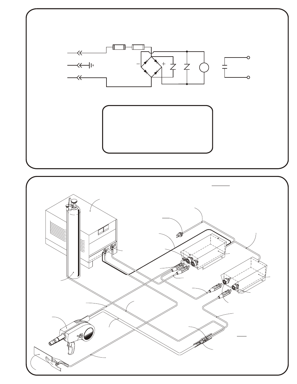
F1
115 V
AC/DC
SR
1
AC
VR1
ELEC. +
GUN
AC
AEC 200-C CONTACTOR WITH AEC 200-2 CONTROL BOX
TO CONSTANT CURRENT POWER SOURCE (DC STICK)
LIMITED WARRANTY - Subject to the terms and conditions hereof, PROFAX, Pearland, Texas warrants its control boxes to be
free from defect in workmanship and material at the time of delivery by PROFAX.
PROFAX will honor warranty claims on this equipment as a result of failure from a defect for a period of one year from date of
sale to the original user.
Upon the return of this unit at users expense, PROFAX reserves the right to either repair or replace as necessary.
This is the only warranty either expressed or implied covering this unit.
To install:
To connect AEC 200-C Contactor to AEC 200-2 Control Box
1. Insure that AEC 200-2 Control Box has been disconnected from all power.
2. Remove top cover from AEC 200-2 Control Box.
3. Install 3-conductor cord from the AEC 200-C Contactor Box to the AEC 200-2 Control Box
at terminals 3 & 4 on TS2. Green wire connects to ground stud.
4. Connect a short section of welding cable between the “Machine Pos.” terminal of the
AEC 200-C Contactor and the “Gun” terminal of the AEC 200-2 Control Box.
5. Connect the power cable lug of the AEC 200 Welding Gun to the “Gun” terminal on the
AEC 200-C Contactor.
6. Recheck all above steps and re-install cover on AEC 200-2 Control Box.
CAUTION
Disconnect all electrical power to
the welding power source before
installing this control unit.
CAUTION
Due to the design of the magnetic blow-out,
welding current polarity must be properly
connected or permanent damage to contacts
may result. Consult wiring and cable connection
drawing below in fig. 1A.
AEC 200-C
Warranty
AEC 200-C
AEC 200-C
Warranty
Warranty
R1
W
VR2
POWER
SOURCE
POSITIVE
OUTPUT
TERMINAL
SENSOR LEAD TO
NEGATIVE OUTPUT
TERMINAL ON POWER
SOURCE
115 VOLT AC
*PLUG NOT INCLUDED
115 VOLT AC
POWER CABLE
“GUN”
RECEPTACLE
“GUN”
RECEPTACLE
“MACHINE POS.”
RECEPTACLE
WELDING CABLE TO
“GUN” STUD ASSEMBLY
ON CONTACTOR BOX
CONNECTION
BOX
CABLE
BOOT
WORK
MODEL
AEC 200
SPOOL GUN
MULTI CONDUCTOR
CABLE TO TERMINAL
STRIP IN CONTROL BOX
WELDING CABLE FROM
NEGATIVE OUTPUT TERMINAL
ON POWER SOURCE
GAS & WELDING
CABLE
HOSE TO GAS
SUPPLY
“ELECTRODE”
RECEPTACLE
SHORT JUMPER CABLE
AWG #1 WITH MALE
DINSE CONNECTOR
ENDS
MODEL
AEC 200-2
CONTROL
18/3 CONDUCTOR CABLE
CONNECTED TO TERMINALS
3 & 4 GREEN LEAD TO
GROUND IN AEC 200-2
CONTROL BOX
CAUTION
DISCONNECT ALL ELECTRICAL
POWER BEFORE INSTALLING
THIS UNIT.
MODEL
AEC 200-C
CONTACTOR
GAS CYL.
WARNING
DUE TO THE DESIGN OF THE
MAGNETIC BLOW-OUT, WELDING
CURRENT POLARITY MUST
BE PROPERLY CONNECTED OR
PERMANENT DAMAGE MAY RESULT.
FIG. 1A
W