Tr-5000 general operating instructions, Control panel & wiring diagram, Figure no. 2 turning roll alignment – Profax TR-5000 User Manual
Page 5: Caution
3
2
TR-5000 General
Operating Instructions
The PROFAX Turning Roll is designed for light loads, with a maximum load of 2500 lbs. per roll or 5000 lbs. per set.
Tube or vessel work piece sizes are from a minimum of 4” dia. to a maximum of 48” dia.
All mounting surfaces must be level and flat.
Turning roll alignment is shown in figure 2. It is important that the distances of the turning roll axles from the mounting surface (X, Y, A, & B)
are the same for all axles. The rolls of the idler unit must be parallel to the rolls of the power unit (see dimensions C=D). Also the rolls must
be 90 degrees to the center line of the vessel or pipe that is to be turned. If any of the above are incorrect the vessel or pipe will creep off in
one direction or the other. Although it is almost impossible to obtain perfect alignment, with care, creeping can be held to a minimum.
Keeping in mind that very few cylinders are perfectly round, the irregularities of the cylinder will cause it to creep in one direction or the other.
This can cause a dangerous condition if not monitored closely. Be sure to rotate a cylinder a number of times while closely monitoring its
creep before starting a weld procedure.
Warning! Use equipment of a proper size to lift and/or move the weldment onto the turning rolls. Falling equipment can cause personal injury
and/or equipment damage.
®
®
®
®
Figure No. 2 Turning Roll Alignment
90°
90°
C
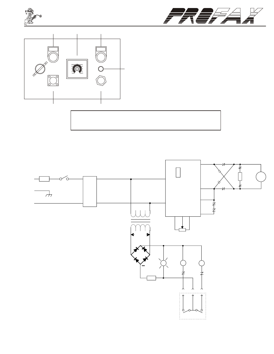
Control Panel & Wiring Diagram
Floor must be
Level and Flat
Vessel or Pipe
Center Line
B
A
X
Y
D
Maintenance
The turning rolls require little maintenance other than periodical removal of spatter and dirt. Inspect the tur ning rolls periodically for nicks or
gouges in the rubber wheels. Replace wheels when damaged. A damaged wheel can cause erratic and/or unstable movement of the work
piece. Proper adjustment of drive roll should be maintained to prevent wheel slippage.
Wiring Schematic
Service or repair of this unit must be done by qualified personnel only.
Warning! Before performing any maintenance on this control circuit disconnect the unit from any power supply.
1. Power On: Indicate of power.
2. Speed Control: Provides control of rotation speed from
0%(0 RPM) to 100%(8 RPM).
3. Power ON/OFF: Power Switch “ON” or “OFF”
4. Foot Switch: Plug-in for the foot switch to start and stop the rotation.
5. Power in
6. Fuse
CAUTION!
OVERLOADING of the turn rolls can cause
slippage and damage to the wheels and drive components.
Make sure that the work piece does not exceed a maximum
of 5000 lbs.
CAUTION! - Switching rotation direction before coming to a complete
stop may damage motor and/or gear box voiding warranty.
4
5
6
SPEED
POWER
0FF ON
POWER ON
POWER IN
AC110V
FOOT SWITCH
1
2
3
12
+
5K
0
CR1
1
4
2
F2
1A
10A
CR2
21
20
19
F1
10
9
8
A
CR1
P
R2
11
I
1
R
8
7
13
14
CR1
N
O
I
S
E
F
I
L
T
E
R
T1
CR2
8
CR1
CR1
CR2
CR2
CR1
CR2
+A
-A
+F
-F
SR1
AC
AC
L1
L2
F3
PCB
L1
L2
GND
Power
SW1
23
M
RC1
F
R
FORWARD
REVERSE
CR2
REMOTE
FOOT SWITCH
28
26
25
24
27
24VAC
CT1
5
6
5
6
Line voltage is 115VAC
for the TR-5000 and 220V
for the TR-5000-2