Wp-500 parts list, Daily maintenance – Profax WP-500 User Manual
Page 6
®
®
4
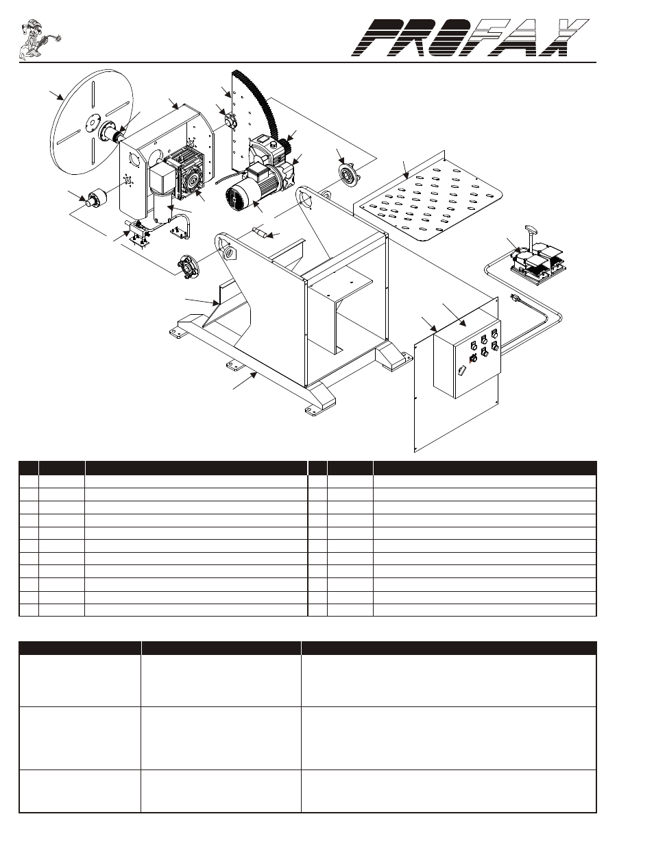
WP-500 Parts List
TROUBLE SHOOTING
1. No power
1. Check power supply for 110VAC 50/60Hz.
Indicator Light Fails to light
2. Fuse blown
2. Check and replace fuse.
3. Faulty indicator light
3. Check and replace indicator light.
4. Faulty power switch
4. Check and replace power switch.
1. Tilt/Rotate switch in TILT position
1. Change to “Rotate”.
2. VR set at 0 position
2. Adjust it.
Table fails to turn
3. Foot switch
3. Check and replace Foot switch.
4. The Relay R3, R4
4. Check and replace R3, R4.
5. Circuit board
5. Check and replace.
Table will not tilt
1. Tilt/Rotate switch in Rotate position 1. Change it to “Tilt”.
2. The Relay R3, R4
2. Check and replace.
3. Circuit board
3. Check and replace.
PROBLEM
POSSIBLE CAUSE
SOLUTION
NO. PART NO. DESCRIPTION
1.
PX9997
Table
2.
PX7000
Table Shaft
3.
PX7001
Tilt Base
4.
PX9995
Table Motor
5.
PX9959
Tilt Gear
6.
PX7002
Tilt Gear Shaft
7.
PX9957
Pinion Gear
8.
PX9956
Tilt Gear Box
9.
PX7003
Tilt Bearing
10. PX7005
Top
11. PX9994
Motor Tilt
NO. PART NO. DESCRIPTION
12. PX9960
Table Gear Box
13. PX7006
Table Ground
14. PX7007
Tilt Shaft
15. PX9996
Limit Switch
16. PX7010
Cover Plate Rear
17. PX9955
Control Box Complete
18. PX9991
Cover Plate Front
19. PX9958
Base
20. PXCFS404 Foot Switch
21. PX9984
PC Board Fuse 10A 5mm x 20mm (Not Shown)
22. PX9967
Fuse Main Power 10A (Not Shown)
1
13
16
18
17
10
8
9
15
11
12
3
2
4
6
5
7
20
19
14
®
®
Daily Maintenance
*NOTE: INSPECT & REPAIR BEFORE OPERATION.
• Inspect table ground for proper ground tension against table. (Positioners)
• Check oil level in gear cases & fill if necessary. (WP-500/WP-1000/WP-2000)
• Inspect foot pedal and/or pendant for proper operation.
• Test limit switches if applicable.
• Test operation of power switch and/or emergency stop button.
• Check for any broken wires, loose connections, worn parts or damages before operation.
• Apply grease to all gears and grease fittings. (Weekly)