Posiflex PD–73X1 User Manual
Page 5
Part 5
tube of PD-7301/7311/7321 close against the
side wall of HT or PB chassis. Match the 2
cylindrical locating bosses into 2 round holes
in the I/O plate. The side of PD-
7301/7311/7321 base with the screw holes
shall face against the sidewall of HT or PB
system chassis. Use the self-tapping screw that comes with PD-
7301/7311/7321 to fix from external side of sidewall as demonstrated in the
above picture. Carefully close back the top cover of HT or PB system and
connect the interface cable of PD-7301/7311/7321 to appropriate port in HT or
PB connector area. Then close the back cover of HT or PB system. Please
reserve the pole hole cover from the back cover for future use.
COMMAND EMULATION MODE SETUP
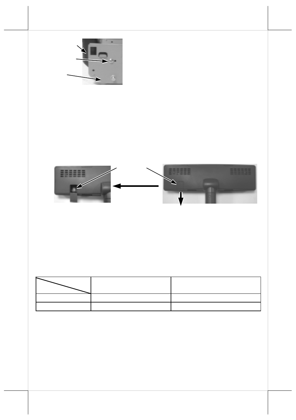
On control board in display head
Now please check the back of PD-7301/7311/7321 display head as in
the right picture above. There is a small piece of plastic cover for the “DIP
switch window”. Slide the cover downward but don’t pull it off otherwise you
may have to practice for inserting it back. You can find 2 positions of DIP
switches in this window. Adjust for the appropriate command mode used by
the application program according to below table if required. Switch position
counts from left to right and “ON” means pushed up as indicated in the left
picture above.
SW2
SW1
OFF ON
OFF
Epson 2 x 20
Noritake 2 x 20
ON
Epson 4 x 26
IEE (Chinese) 2 x 10
The factory default command mode for PD-7301 is set to Noritake
mode. If the switch is set to IEE mode for PD-7301 all “Chinese characters”
will be displayed in full dots since it is not applicable. The factory default
command mode is set to IEE mode for both PD-7311 and PD-7321.
Fixing screw
HT or PB
chassis sidewall
PD-73X1 Base
DIP switch
window