Using the customer display – Posiflex PD-2605UE User Manual
Page 4
Part 4
COMMAND EMULATION MODE SETUP
(FOR PD-2605)
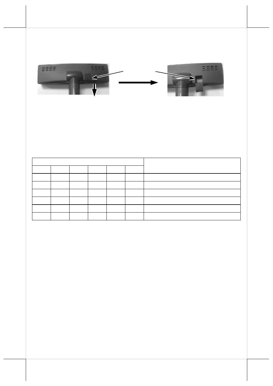
Now please check the back of PD-2605 display head as in the above left
picture in Pix. 3. There is a small piece of plastic cover for the “DIP switch
window”. Slide the cover downward but don’t pull it off otherwise you may
have to practice for inserting it back. You can find 6 positions of DIP
switches in this window. Adjust for the appropriate command mode used by
the application program according to below table. Switch position counts
from left to right and “ON” means pushed up as indicated in the above right
part in Pix. 3.
Switch Position
1
2
3
4
5
6
Command Mode
ON
OFF OFF
ON
OFF OFF
ADM
ON
OFF
ON
ON
OFF OFF
Aedex
ON
OFF
ON
OFF OFF OFF
Epson
ON
OFF OFF
ON
ON
OFF
Futaba
ON
OFF
ON
OFF
ON
OFF
Noritake
ON
OFF
ON
ON
ON
OFF
UTC
The factory default command mode is set to Noritake mode for normal
delivery. Please change it to Epson mode if OPOS or UPOS driver is used for
the application program.
POWER ON SIGN
With interface cable connection well installed (and with COM port power set
for serial models), turn on the Posiflex POS system, a firmware identifier as
power on sign will appear on the pole display screen for a while to indicate
that pole display is self-tested O.K. and ready to work.
USING THE CUSTOMER DISPLAY
INTERRFACE SELECTION
This series of customer display is designed to serve in Posiflex POS systems
with RS232 interface models and with USB interface models. It is advisable to
well study the I/O port availability of the host system before determining
which interface model to be used.
DIP switch
window
Pix. 3