Integrated amplifiers, Installation and wiring, Input connections microphone input – Paso Sound T3115BGM User Manual
Page 5: Wiring cable, Fig. 5 amplifier rear panel view, Fig. 5a - rear panel mic input terminals, Fig. 5b - rear panel mic input terminals, Page 5, T3115bgm
PAGE 5
SPECIFICATIONS ARE SUBJECT TO CHANGE WITHOUT NOTICE
T3115/3130/3160BGM
INSTALLATION AND WIRING
PROFESSIONAL AUDIO & SOUND
®
INTEGRATED AMPLIFIERS
INPUT CONNECTIONS
MICROPHONE INPUT
MICROPHONE TYPE
The Microphone Input accept Low Impedance (250-600 ohm)
Microphones. The Microphone may be a balanced output type
(three wire) or an unbalanced output type (two wire).
PASO MICROPHONES
All PASO low impedance Microphones have a balanced output for
best performance. Connect the RED lead to terminal HOT, the
WHITE lead to terminal COM and the SHIELD to terminal G (see
Fig. 5A).
CAUTION
TO PREVENT POSSIBLE DAMAGE TO SPEAKERS OR THE
AMPLIFIER ALL INPUT CONNECTIONS MUST BE MADE WITH
THE AMPLIFIER OFF (POWER OFF).
WIRING
CABLE
CLASS 2 WIRING ACCEPTABLE
SER. NO.
COM
70V
MUTE
GROUND
LINE FUSE
1.6A 250 V
CAUTION; TO REDUCE THE RISK OF FIRE OR SHOCK DO NOT
EXPOSE THIS APPLIANCE TO RAIN OR MOISTURE. DO NOT
REMOVE COVER. THERE ARE NO USER SERVICEABLE PARTS
INSIDE. REFER SERVICING TO QUALIFIED SERVICE PERSONNEL.
CAUTION: TO REDUCE THE RISK OF FIRE,
REPLACE ONLY WITH SAMETYPE OF
FUSE.
ATTENTION: AFIN DE
REDUIR LE RISQUE
D©INCENDIE, REMPLACER
SEUL PAR UN FUSIBLE DE
MEME TYPE.
MOH OUTPUT
LEVEL
AUX
47K ohm 200 Mv
IN PARALLEL
ATTENTION: POUR REDUIRLES RISQUES D© INCENDIE OU
DE CHOC ELECTRIQUE, NE PAS EXPOSER A LA PLUIE OU
L©HUMIDITE, NE PAS ENLEVER LE COUVERCLE. AUCUN
REGLAGE A L©INTERIEUR. POUR REPARATION
CONSULTERUNE PERSONNE QUALIFIEE
117V 60 Hz
500 W MAX.
UNSWITCHED
A
MPLIFIER
POWER RATING
SUPPLY VOLTAGE
POWER CONSUMPTION
15 W RMS
117V 60 HZ
570 VA
T3115BGM
8 OHM
1 WATT
8
25V
600 ohm
1 Volt
AUX
ATTENUATOR
L
R
TEL OUTPUT
LEVEL
600 OHM
100 MV
10K OHM
1 V
250 OHM
1 MV
TEL
MIC
PROGRAM
G
HOT
COM
G
HOT
COM
G
HOT
COM
UNMUTE G
BALANCED
BALANCED
BALANCED
MOH OUTPUT
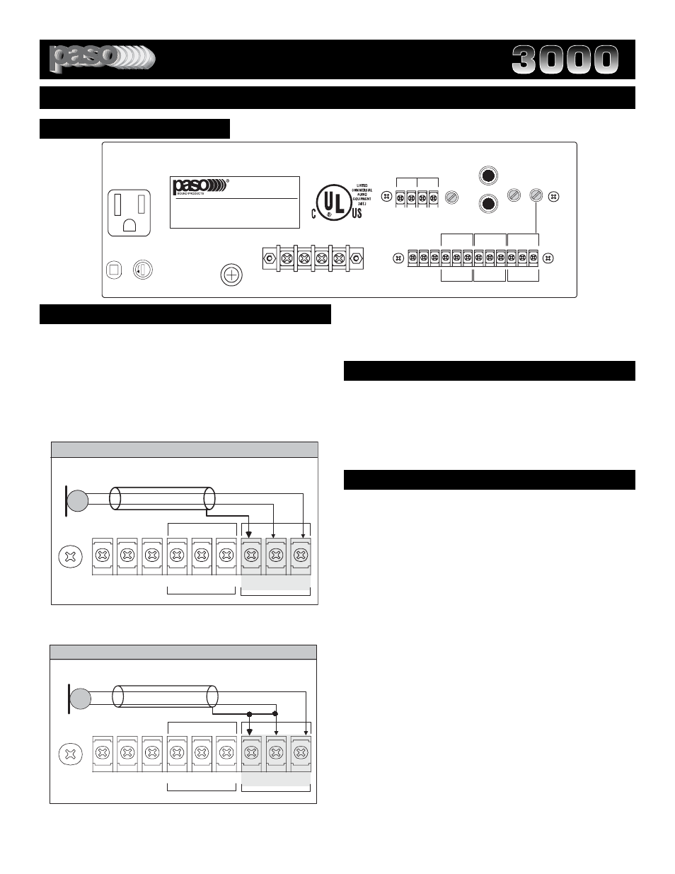
Fig. 5 Amplifier Rear Panel View
3115micbal
The microphone lead color refers to Paso Microphones only. When using
other microphone brand refer to instructions packed with the unit.
G
UNMUTE
PROGRAM
COM
HOT
SHIELD
MIC
RED
BALANCED
MIC
THREE LEADS BALANCED MICROPHONE WIRING
G
COM
HOT
BALANCED
G
MUTE
WHITE
3115micunbal
The microphone lead color refers to Paso Microphones only. When
using other microphone brand refer to instructions packed with the unit.
SHIELD
MIC
RED
TWO LEADS UNBALANCED MICROPHONE WIRING
WHITE
G
UNMUTE
PROGRAM
COM
HOT
BALANCED
MIC
G
COM
HOT
BALANCED
G
MUTE
Fig. 5A - Rear Panel MIC Input Terminals
MICROPHONE INPUT
Attach the microphone leads to the terminal strip as per diagram
in Fig 5A or Fig. 5B.
DO NOT GROUND THE MICROPHONE CABLE SHIELD TO THE
CHASSIS OF THE AMPLIFIER
Fig. 5B - Rear Panel MIC Input Terminals
BALANCED MICROPHONE
IMPORTANT NOTE: The use of an unbalanced Microphone (two
leads) is not recommended. For best results in a PA Application
always use a Unidirectional, Low Impedance, Balanced
Microphone (three leads).
CABLE LENGTH - If the distance between the Microphone and
the Amplifier Input is greater than 15 ft (4.5 m) a Balanced
Microphone must be used. Use a two conductor shielded wire and
connect Microphone to Amplifier as per Diagram in Fig. 5A.
MICROPHONE CABLE ROUTING - The Microphone Cable
should be carefully routed. Improper Cable routing will cause spu-
rious oscillations, regenerative noises, hum, etc. that may perma-
nently damage the Amplifier.
Do not route cable next to power lines.
Do not route cable near or over Fluorescent Fixtures.
Do not route cable next to Speaker Wires.
Do not install cable inside Power Line Conduits.
Avoid the use of staples that may penetrate the cable.
UNBALANCED MICROPHONE
Attach the Microphone leads to the terminal strip as per diagram
in Fig 5B.
Be sure the cable length does not exceeds 15 Ft. (4.5 m).