Integrated amplifiers – Paso Sound T3115BGM User Manual
Page 18
PROFESSIONAL AUDIO & SOUND
®
PAGE 18
Specifications are subject to change without notice
T3115/3130/3160BGM
INTEGRATED AMPLIFIERS
INSTALLATION AND WIRING
OUTPUT CONNECTIONS
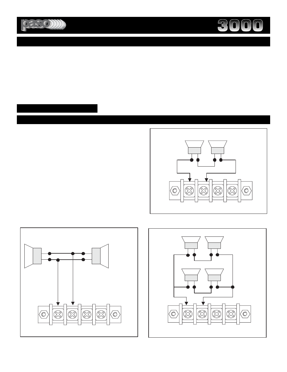
SERIES - PARALLEL - SERIES PARALLEL INSTALLATIONS
In applications requiring a small number of speakers, the speaker
line can be connected to the 8 ohm impedance output of the
Amplifier. The speakers available should be wired either in series,
parallel or series parallel combinations to match the output imped-
ance of 8 ohm. Impedance matching is essential to provide maxi-
mum power transfer and efficiency.
CAUTION
1) If the total load impedance of the speakers used is greater than
8 ohm less then the total power of the amplifier will be transferred
to the speakers.
2) If the total load impedance of the speakers used is lower than 8
ohm the mismatch will cause an overload of the output and may
trip the Amplifier Overload Protective System.
Fig. 18B - Series-Parallel Connection Diagram
PRECAUTIONS: THE AMPLIFIER UTILIZES A BALANCED SPEAKER OUTPUT SYSTEM ON BOTH 8 OHM AND 25/70
VOLT SYSTEM OUTPUTS.
1) DO NOT CHASSIS GROUND THE SPEAKER OUTPUT TERMINALS.
2) MAKE SURE THAT THE SPEAKER WIRES ARE NOT SHORTING OUT AT THE TERMINAL STRIP.
3) MAKE SURE THAT THE OUTPUT TERMINALS PROTECTIVE COVER IS REPLACED AFTER ALL THE SPEAKER
WIRING AND CONNECTIONS ARE COMPLETED.
4) PRIOR TO THE INSTALLATION AND WHEN USING THE 70 VOLT LINE SYSTEM CHECK THE LOCAL ELECTRICAL
CODES REGULATING THE WIRING OF THE SYSTEM.
spkout03
8 ohm
+
-
+
-
+
-
+
-
8 ohm
8 ohm
8 ohm
COM
8
25V 70V
LOW IMPEDANCE SYSTEMS
spkout01
COM
8
25V 70V
16 ohm
16 ohm
+
+
-
-
Z Load
=Z Spkr 1
-----------------
2
Fig. 18A - Parallel Connection Diagram
Fig. 18 - Series Connection Diagram
spkout04
+
-
+
-
4
ohm
4
ohm
COM
8
25V 70V
Z Load
=Spk 1 + Spk 2