G4 graniterack iscsi storage server quick guide – OpenEye G4 GraniteRack Quick Start User Manual
Page 2
32136AB
Copyright ©2013 OpenEye. All Rights Reserved. Information contained in this document is subject to change without prior
notice. OpenEye does its best to provide accurate information but cannot be held responsible for typos or mistakes.
23221 E Knox Ave
Liberty Lake, WA 99019
1.888.542.1103
G4 GRANITERACK iSCSI STORAGE SERVER
Quick Guide
POWER
Operating Temperature Range
32˚F~104˚F (0˚C~40˚C)
To reduce the risk of electrical shock or damage to the equipment:
•
Do not disable the power grounding plug. The grounding plug is an impor-
tant safety feature.
•
If the electrical plug you are using does not have a ground plug recep-
tacle, contact a licensed electrician to have it replaced with a grounded
electricl outlet.
•
Plug the power cord into a grounded electrical outlet that is easily acces-
sible at all times.
•
Disconnect the power from the recorder by unplugging the power cord
either from the electrical outlet or the recorder.
INSTALLING THE FRONT BEZEL
If you choose to mount the front bezel onto your
G4 GraniteRack you will need to remove the
attached handles and attach the bezel before
attaching the rackmount rails.
1. Remove the two screws from each handle.
2. Install the included bezel clips and fasten
with screws.
3. Align and slide the right side of the bezel
into the right clip.
4. Slide the left side of the bezel into the left
clip.
5. Lock the bezel by turning the key counter-
clockwise.
1
2
1
2
1
2
LOGGING IN
OpenEye recommends changing the username and password for your G4 GraniteRack. The
default Username and Password are as follows
Username: DVRAdmin
Password: dvr4321
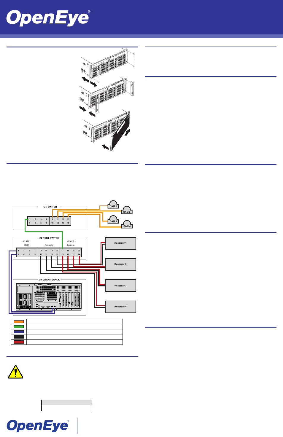
CONNECTION DIAGRAM
IP cameras to PoE switch
PoE switch to 24-port switch
G4 GraniteRack to 24-port switch
Recorder to 24-port switch
24-port switch to recorder
CREATING iSCSI TARGET ACCOUNTS
OpenEye recommends creating a separate target volume for each recorder on your system.
1. Click
Start > All Programs > Administrative Tools > Microsoft iSCSI Software Tar-
get.
2. Click
Yes.
3. Right-click in the
Virtual Disk field, and then click Create iSCSI Target.
4. This will open the
iSCSI Target Wizard. Click Next to continue.
5. Type your
iSCSI Target Name.
Note The iSCSI Target Name must consist of lowercase letters and numbers only. No
spaces, special characters, or underscores may be used. For example:
n1.3, mean-
ing “NVR1 with 3TB storage.”
6. Type an effective description of the target.
7. Type the
IP Address of the recorder you are assigning to this volume in the IQN field,
and then click
Next.
Note The iSCSI Qualified Name (IQN) allows the iSCSI target to identify the iSCSI initiator
requesting access. OpenEye recommends using the IP address of the connecting
recorder, but you can also use the MAC address or DNS name.
8. Click
Next, and then click Finish.
CREATING VIRTUAL DISKS
Create a virtual disk for each recorder on your system.
1. In the iSCSI Target window, click
Devices.
2. Right-click the
Devices List field, and then click Create Virtual Disk.
3. This will open the
Create Virtual Disk Wizard. Click Next to continue.
4. Type the location in the
File field.
Note The location name should be the same as the iSCSI Target Name. The location should
be formatted as E:\{iSCSI Target name].vhd.
5. Set the
Size of the Virtual Disk (in megabits).
6. Type an effective
Virtual Disk Description.
7. To assign a recorder client to the volume, click
Add.
8. Select the target recorder.
9. Click
Next, and then click Finish.
RECORDER CONFIGURATION
Once your G4 GraniteRack is connected and set up, you will need to configure the iSCSI
unit and the recorder to communicate with each other.
CONFIGURE THE GRANITERACK TO COMMUNICATE WITH THE RECORDER
1. On the
iSCSI Initiators tab, click Identifier Type, and then select IP Address.
2. Type the IP address of your recorder in the
Value field.
3. Click
OK.
4. Click
OK again.
CONFIGURE THE RECORDER TO COMMUNICATE WITH THE GRANITERACK
1. Restart your recorder in Windows mode.
2. Click
Start, and then type iSCSI Initiator in the Search field.
3. Click
iSCSI Initiator.
4. In the
Target field, type the IP address of your G4 GraniteRack.
5. Click
Quick Connect. Once completed, the status will read “connected.”
6. Click
Done.
7. Click the
Volumes and Devices tab.
8. Click
Auto Configure.
9. Click
OK.
SET THE VOLUME SIZE
The volumes you have created on your G4 GraniteRack will be seen by your recorder as
blank hard disks. In order to save video, you must first format the disks.
1. Click
Disk Management.
2. In the
Initialize Disk window, select GBT.
Note GBT supports drives that are 3TB or larger, providing a large volume size for
maximum storage capacity.
3. Click
OK.
4. Right-click
Unallocated Volume, and then click New Simple Volume.
5. Click
Next.
6. Type the
Volume Size (in MB), up to 3TB (3,000,000 MB).
Note OpenEye recommends a maximum volume size of 3TB.
7. Click
Next, and then click Next again.
8. Click
Allocation Unit Size, and then select 64K.
9. Click
Volume Label, and type DVR.
10. Click
Next.
11. Click
Finish.
A single G4 GraniteRack can be connected to up to 25 network video recorders to provide
up to 64TB of pooled storage.
To connect a G4 GraniteRack to one or more recorders, you can purchase a 24-port switch
from OpenEye. This switch comes preconfigured with Gigabit networking and LACP.
Ports 1-8 are to be used for iSCSI connection. When connecting a G4 GraniteRack, use
2 connections per unit (1 and 2, 3 and 4, 5 and 6, 7 and 8, respectively). Ports 9-16 are to
be used to connect the recorders, and ports 17-24 can be used to connect cameras to the
recorders, if necessary.