Olson Technology OTR-3550-DC User Manual
Page 6
025-000187 REV B
Page 6
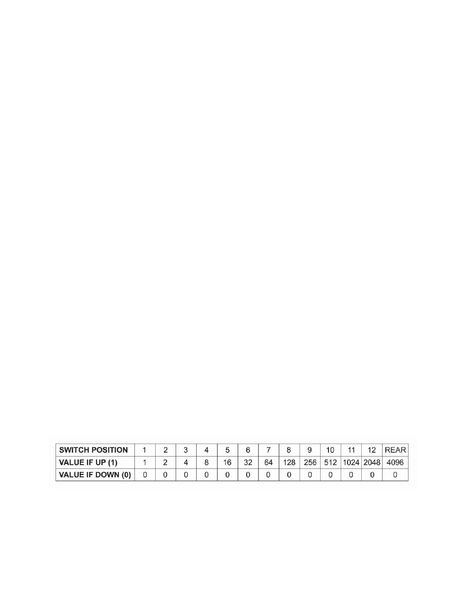
Using the values shown in Table 1, move DIP switch positions UP until the total of the UP positions
equals the number “N”.
The easiest way to do this is to work out the settings on paper.
Subtract from “N” the largest position value possible (and note the position as a “1”), then repeat this
using the remaining value(s) of “N” until the remainder is exactly zero. Note switch positions used to
add to the total value as “1” and the positions NOT used as “0”.
C)
Use your paper notes of which positions are “1” and which are “0” to set the DIP switch positions for
the desired frequency.
D)
Set the 6-position band selection DIP switch for the proper frequency range using Table 2 below.
BAND SELECT
DIP SWITCH FREQUENCY RANGE
1 0 1 1 1 1
-
48 MHz to 168 MHz
1 1 0 1 1 1
-
169 MHz to 447 MHz
1 1 1 0 1 1
-
448 MHz to 855 MHz
Table #2 BAND SELECTION DIP SWITCH VALUES
TO COMPUTE THE CORRECT SETTINGS FOR OUTPUT FREQUENCIES:
A)
Determine the video carrier frequency of the desired channel (which must end in .00, .25, .50, or .75).
B)
Compute the number “N” needed to work out switch codes:
Use the formula, N = (605.75 + F
c
)4 Where F
c
= channel video carrier frequency.
Set the DIP switches and the rear panel toggle switch to = “N” as a binary number:
Each switch position has an equivalent value as indicated in Table 3. A switch position is either UP =
OFF = (VALUE) or is DOWN = ON = (0).
Table # 3. OUTPUT CHANNEL SELECT DIP SWITCH VALUES