Olson Technology OTR-3550-DC User Manual
Page 4
025-000187 REV B
Page 4
4)
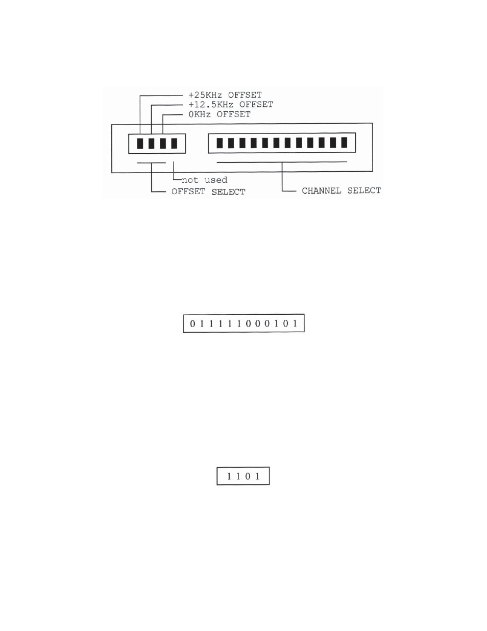
OUTPUT CHANNEL SELECTION - MODULATOR SECTION
Remove the front panel plate marked “Output Channel Select” to expose the channel select and offset select DIP
switches as shown in Figure #2.
Figure #2 - OUTPUT CHANNEL SELECT DIP SWITCHES
The OTR-3550-DC has a rear-panel toggle switch which is also used in setting output frequency.
A)
CHANNEL SELECTION - Channel selection is accomplished by properly setting the 12-position
DIP switch to the correct code. Switch codes can be selected from Table 5 at the rear of this
manual. Set the DIP switches from left to right as shown in the table. For example, if channel DS-1
is selected, its corresponding switch code is:
B)
OFFSET SELECTION - Although it may not be required in PAL D China applications, the
OTR-3550-DC has a feature which allows output channels to be offset from their nominal frequency.
Fixed offsets of +12.5 KHz and +25 KHz are available in addition to operation on the nominal channel
frequency (+0 KHz offset).
If offset output frequencies are desired, the 4 position DIP switch must be set properly. The +0 KHz,
+12.5 KHz, or +25 KHz position of the 4-position switch must be moved to the down position - all
other positions must be in the up position. These positions are identified in Figure 2.
For example, if 0 KHz offset (normal operation) is desired, the proper switch settings would be:
The fourth position of this switch is not used. Settings for this switch are not shown in Table 5.
C)
OUTPUT CONNECTION - The output signal is present at the RF output connector. This unit has an
output test point which is useful when recording operating levels, trouble-shooting, etc. The RF test
output is approximately 20 dB below the main output. Reference readings may be taken at the RF test
output after the output level is properly set for the system.