Olson Technology OTOHP-NMS Mini User Manual
Page 3
INTRODUCTION
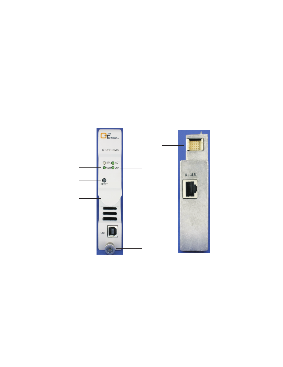
OPERATION PANEL DESCRIPTIONS
The components and features of the OTOHP-NMS module are described below.
The OTOHP-NMS equipment management module is mounted in the first (left) slot of
the OTOHP platform to provide local monitoring and configuration, as well as remote
management. The OTOHP-NMS module is able to communicate with the rest of the
modules via USB port for local access or RJ45 Ethernet port for remote access. The
OTOHP-NMS module provides an NMCP (Network Management Console Program) for
monitoring and configuration along with a PC compatible graphical user interface (GUI).
The OTOHP-NMS integrates the SNMP protocol and the SCTE-HMSMIB’s for remote
access via a standard SNMP agent.
1. STA LED:
Green indicates the module is accessing data through RJ-45 port. No
light indicates the module is not accessing data.
3. USB LED: Green indicates that the USB port is connected to a PC. No light
indicates the USB port is not connected to a PC.
4. LNK LED: Green indicates the Ethernet port is connected to a PC. No light indicates
the Ethernet port is not connected to a PC.
6. Reset: Push button; when pushed, this button causes the module to reset.
Green indicates the module is working properly. Red indicates at least
one of the 8 fans of the OTOHP-CH chassis has failed
2. ACT LED:
1
2
3
5
4
6
8
7
9
11
10