Olson Technology OTOHP-FTX User Manual
Page 5
INSTALLATION (CONT.)
FRONT PANEL NUMERIC DISPLAY OPERATION DESCRIPTION
7
Using a signal level meter measure the RF input at the RF TP test point 20dB
below actual level on the front panel and verify that it is set at the specified value
for that channel Further adjust the RF input level if required
8
Verify that the correct optical connector will be attached to the optical connector on
the module Clean both the bulkhead and fiber connectors CAUTION: Using
mismatched optical connectors will damage the connectors and degrade system
performance. Ensure that each fiber has a matching connector.
9. Connect the optical fibers to the appropriate OPT OUT connection on the rear
panel Then turn on the laser from the front panel instructions are below
10. Use an optical power meter to verify that the optical output level meets
specifications
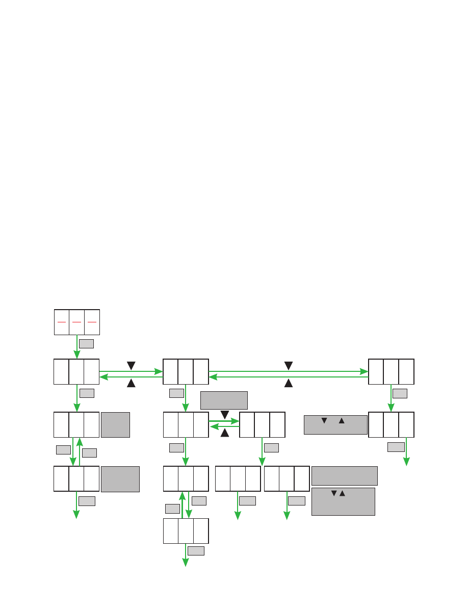
First push SET on the LED display and set function.
.
,
-
(
)
.
.
.
.
.
.
(
).
.
A01: Laser on/off menu
A02: AGC/MGC setting menu
A03: Alarm menu
A01
O
O
10
F
FF
F
4
1
A02
2
ON F
O F
A
0
0
0
3
3
SET
AGC On = Display Off
AGC Off = Display 00
Indicates
Laser
OFF
Indicates
optical
power (dBm)
1 = AGC Mode
2 = MGC Mode
Push and to view
the alarm code.
Push ,
and SET
to set the MGC Value
if AGC = Off
00
SET
SET
SET
SET
SET
EXIT
EXIT
EXIT
EXIT
EXIT
SET
SET
SET
SET