Olson Technology OTOHP-CH User Manual
Page 5
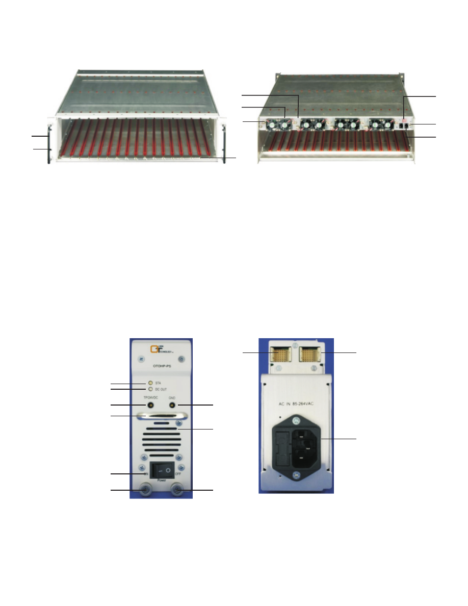
OPERATION PANEL DESCRIPTIONS
The components and features of the chassis and power supply are described below.
1.
Handle: For handling the chassis when installing or uninstalling from the rack.
2.
Mounting hole (four locations): Fixes the chassis to the standard rack.
3.
Chassis backplane: Provides signal and power connections to modules.
4.
Slot: Guide for application module installation.
5.
Fan: For heat dissipation.
6.
Grounding Screw: For chassis grounding.
7.
ID Selector: Select chassis ID for cascade application.
8.
Grounding Screw: For chassis grounding.
9.
RS-485 Port: Provide connect port for cascade application.
1.
STA LED: Green indicates the module is operating properly. Red indicates the
module has alarms.
2.
DC Out LED: Green indicates the module is putting out DC power. If the LED is
dark, the power supply is not putting out DC power.
1
2
3
4
5
9
7
8
10
11
12
6
2
1
3
4
6
5
7
8
9