2 cabling and wiring – Northern Airborne Technology 270 User Manual
Page 16
Model 270 Universal Interface Amplifier Manual
SM270 Rev. 4.10
2.3.2
Cabling and Wiring
In all installations, use shielded cable exactly as shown and ground as indicated.
Significant problems (particularly with ground loop noise) may result from not following
these guidelines.
All unshielded wire shall be selected in accordance with AC43.13-1B Change 1,
Paragraphs 11-76 through 11-78. Wire types should be to MIL-W-22759 as specified in
AC43.13-1B Change 1, Paragraphs 11-85, 11-86, and listed in Table 11-11. For
shielded wire applications, use Tefzel MIL-C-27500 shielded wire with solder sleeves
(for shield terminations) to make the most compact and easily terminated interconnect.
Follow the block diagram in Section 2.6 as required.
Allow 3 inches from the end of the wire to the shield termination to allow the hood to be
easily installed. Note that the hood is a ‘clamshell’ hood, and is installed after the wiring
is complete.
All wiring should be at least 24 AWG, except power and ground lines, which should be
at least 22 AWG. Ensure that all ground connections are clean and well secured. The
chassis must be grounded to the airframe.
Audio cable shields must be grounded at one end only. If audio cable shields are
grounded at both ends, AC noise currents can flow through the shield and inductively
couple noise into the audio wires. If additional RF shielding is required, use double-
shielded wire with the inner shield grounded at one end and the outer shield grounded
at both ends.
Do not connect the 14 Vdc power and 28 Vdc power inputs at the same time without
external diode isolation to prevent a short circuit between the +28 Vdc and +14 Vdc
power supplies.
2.3.2.1
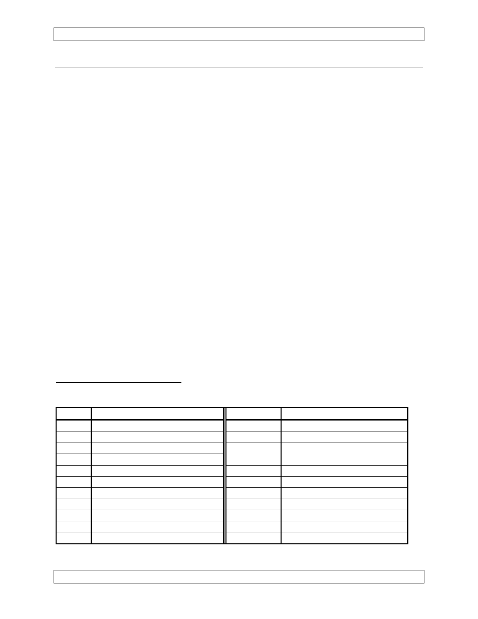
Pin Identification
The following table specifies the functions of the connector pins.
Pin# Function
Pin#
Function
P1-1
28 VDC POWER ***
P1-12
WIPER #2 (relay contact)
P1-2
14 VDC POWER ***
P1-13
SPARE OUT (spare audio)
P1-3
MIC IN HI
P1-14, 15, GROUND RETURN
P1-4
AUDIO OUT HI
20, 21, 23
P1-5
MIC OUT HI
P1-16
MIC IN LO
P1-6
AUDIO IN HI
P1-17
AUDIO OUT LO
P1-7
KEYED INPUT (relay control) P1-18
MIC OUT LO
P1-8
GND/EXT. VOX THLD
P1-19
AUDIO IN LO
P1-9
N.O.#1 (relay contact)
P1-22
N.C.#1 (relay contact)
P1-10 WIPER #1 (relay contact)
P1-24
N.C.#2 (relay contact)
P1-11 N.O.#2 (relay contact)
P1-25
SPARE IN (spare audio)
*** Note: The 14 Vdc and 28 Vdc power inputs are designed for mutually exclusive use.
Page 2-2
Dec 12, 2006
ENG-FORM: 805-0108.DOT
CONFIDENTIAL AND PROPRIETARY TO NORTHERN AIRBORNE TECHNOLOGY LTD.