NIStune Type 2 V.1.6 User Manual
Page 14
Type 2 Hardware Installation Manual
Page 14 of 20
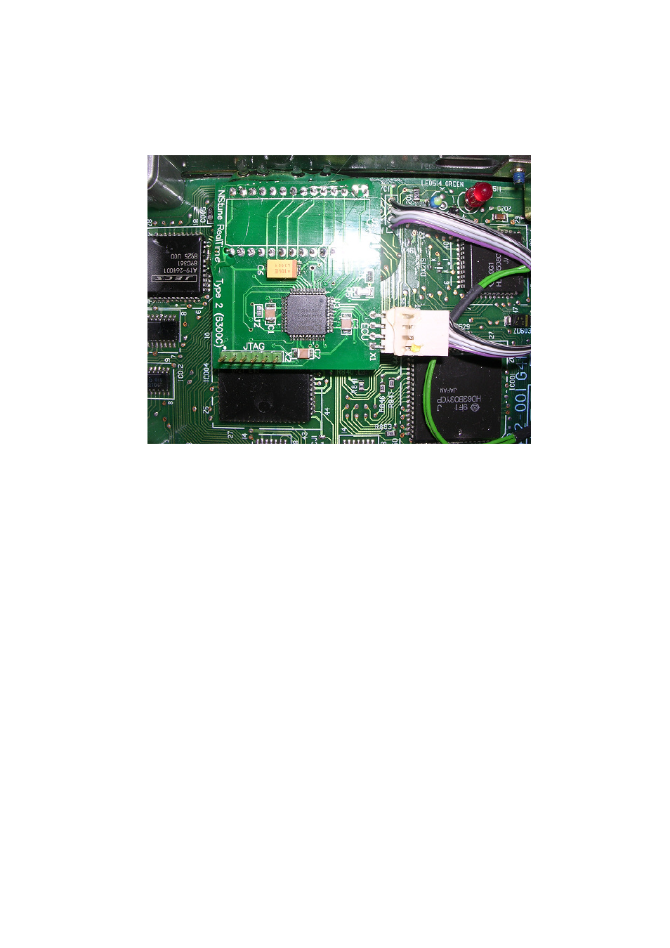
Connector Wire 1 - ECU throughhole R/W (Marked)
Connector Wire 2 - ECU throughhole A14
Connector Wire 3 - ECU throughhole A15
Connector Wire 4 - ECU throughhole E
Install the board into the 28 pin socket and connect the ECU connector. The board is hot glued into
the ECU to ensure connectivity during ECU vibration
Hot glue the corners of the board to the ECU and the connector plug. This ensures that the
board stays installed the EPROM socket and the connector does not come off when the ECU
in the vehicle endures vibration