5 module status 5.1 gpi alarm, Module status outputs, 5 module status – Nevion DA-SDI User Manual
Page 10: 1 gpi alarm – module status outputs
DA-SDI
Rev. H
nevion.com | 10
5 Module status
The status of the module can be monitored in three ways.
1. GYDA System Controller (optional).
2. GPI at the rear of the sub-rack.
3.
LED’s at the front of the sub-rack.
Of these three, the GPI and the LED’s are mounted on the module itself, whereas the
GYDA System Controller is a separate module giving detailed information on the card
status. The functions of the GPI and the LED’s are described in sections 5.1 and 5.2.
The GYDA controller is described in a separate user manual.
5.1 GPI ALARM
– Module Status Outputs
These outputs can be used for wiring up alarms for third party control systems. The
GPI outputs are open collector outputs, sinking to ground when an alarm is triggered.
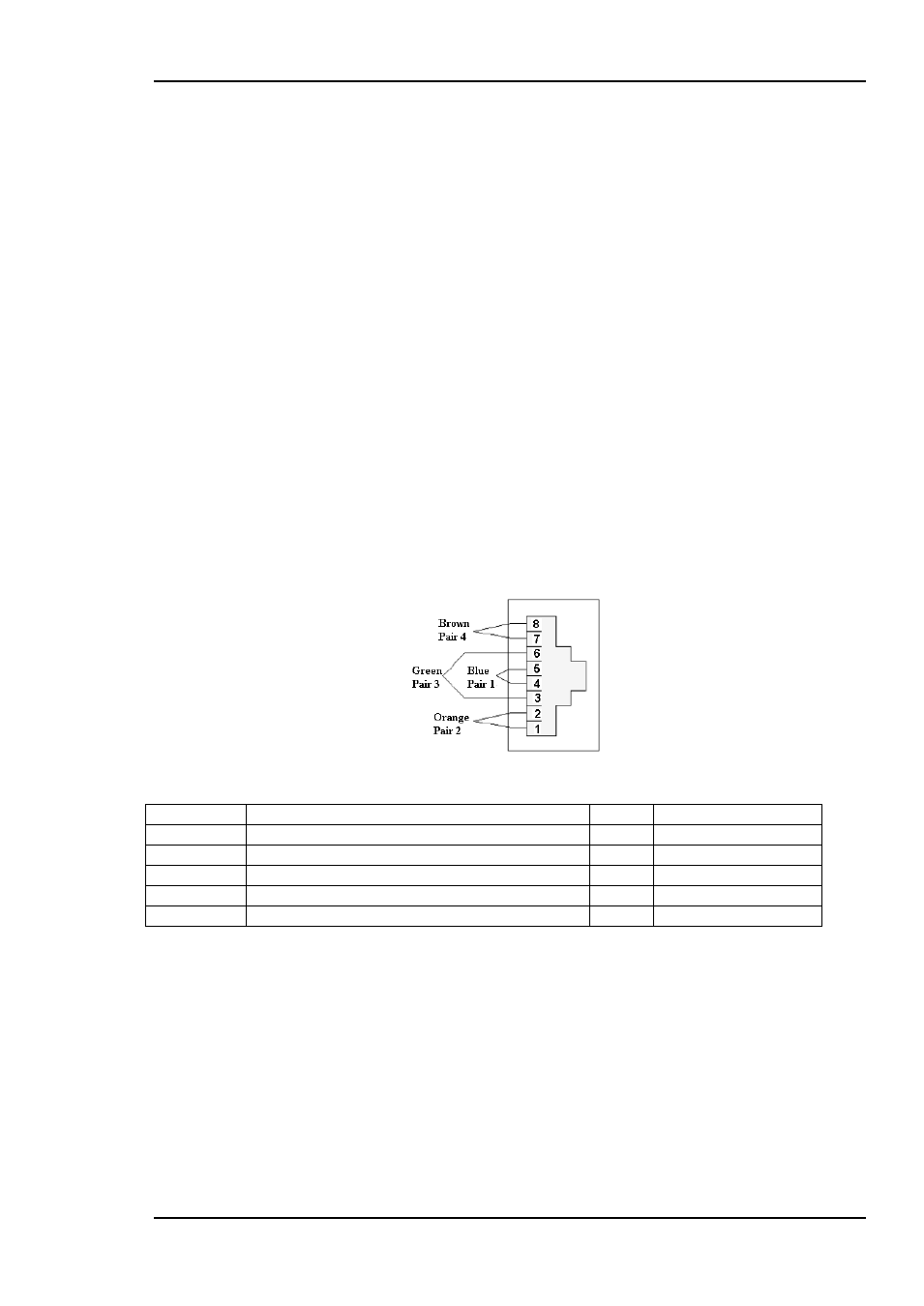
The GPI connector is shown in Figure 8.
Electrical Maximums for GPI outputs
Max current: 100mA
Max voltage: 30V
DA-SDI module GPI pinning (Only supported by DA-SDI-C1 backplane):
Figure 8: GPI Outlet
Signal
Name
Pin #
Mode
Status
General error status for the module.
Pin 1
Open Collector
Rate
Rate SD
Pin 2
Open Collector
LOS
Los Of Signal
Pin 3
Open Collector
LOCK
Reclocker in Lock
Pin 4
Open Collector
Ground
0 volt pin
Pin 8
0V.