3 frame synchronizer, 4 frame synchronizer in ‘frame sync’ mode – Nevion DAC-AVA-DMUX User Manual
Page 22
DAC-AVA-DMUX
Rev. A
nevion.com | 22
when for instance a new source being switched into the signal path, the timing errors
occurring by this change will be corrected if the new timing reference is within +/-1024
samples of the “initial phase signal”. This also goes for all consecutive timing references.
If a signal is more than +/-1024 samples of
f relative to the “initial phase signal”, the output
will repeat the last frame, refill the 2048 samples buffer and take out data from the centre of
the buffer. This new signal is now considered the “initial phase signal”. Audio will fade out
when a frame repeat is being done, and fade in at the new frame.
Hence, it produces an error free video output without frame wrapping when the video input
comes from a router with synchronous input video signals that all lies within +/-1024
samples of each other.
The de-glitcher output is always seamless. When a signal is repeated the audio
is faded out. It fades in at the new frame.
4.3.3 Frame synchronizer
The frame synchronizer consists of a frame store buffer and some control logic. The frame
store buffer can store up to 8 full HD frames. Data is fetched from this buffer according to
the user settings by force of the control logic. The control logic sets the frame synchronizer
into different modes dependent on the presence of a sync input.
4.3.4
Frame synchronizer in ‘Frame sync’ mode
If a sync input (B&B or Tri-level) is present, the frame synchronizer will output a signal that
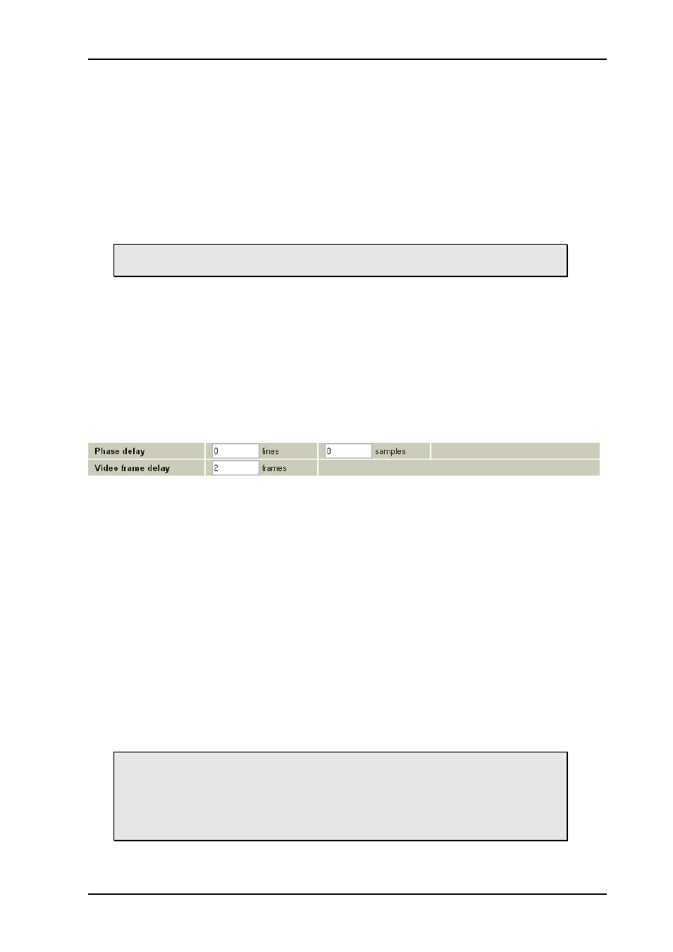
has a delay relative to this signal. Two parameters can be set: "Phase delay" and "Frame
delay".
Figure 12: Multicon GYDA view of the video delay settings
Let us first focus on the phase delay
, which also may be called “output phase delay”. This
parameter can be positive or negative, and determines the relationship between the
outgoing video and the sync signal.
The phase delay can thus be written in several ways, a large positive delay will equal a
small negative delay, because there is wrap-around on a frame basis. It follows that it is not
useful to specify a phase delay larger than 1 frame. Strictly speaking the range could have
been limited to -1/2 frame to 1/2 frame. For convenience, the delay range is allowed to be
from -1 frame + 1100 samples to 1 frame
– 1100 samples.
In addition to the phase delay, the user may specify additional frames delay. When frame
delay is set to 1 frame, the delay through the card will be between 1 and 2 frames,
depending on the input phase between SDI-input and sync input.
The frames and lines are measured in units of the output SDI video standard. If the output
SDI standard is 1080i25, a delay of one line is equal to 35.5us. If the output SDI standard is
720p50, a delay of one line is equal to 26.6us. If the output SDI standard is 625i25, a delay
of one line is equal to 64us.
For a scenario where the card receives different HD video standards, (e.g.
1080i25 and 720p50) the user may want to conserve a specific delay in
microseconds for all HD video standards. This is accomplished by specifying
the delay in number of samples instead of frames and lines. (For HD video
standards the sample frequency is equal over standards, but the line and frame
frequencies are different for the different standards).
If video input disappears