Sdi-td-mux-4 / sdi-td-dmux-4 rev. n, 3 commands intended for debug/lab use only – Nevion SDI-TD-MUX-4 User Manual
Page 25
SDI-TD-MUX-4 / SDI-TD-DMUX-4
Rev. N
nevion.com | 25
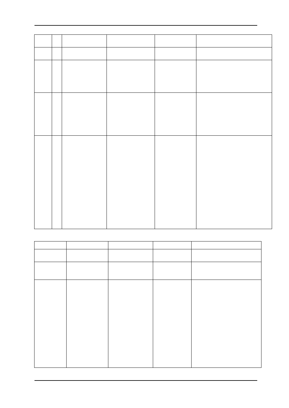
Block Blk
#
Commands
Example(s)
Response
Control
carrier detected or no carrier
detected.
pwr
0-5 -
Power supply monitors
pwr 0 = 5.0V
pwr 1 = 3.3V
pwr 2 = 2.5V
pwr 3 = 1.8V
pwr 4 = 1.2V
rcl
0-3
(4)
-
rcl 0
lock | lol
Reclocker
No commands available, only used to
report lock status. The MUX board
has one rcl block for each SD input,
while the DMUX board has one rcl
block for the HD input (rcl 0) and one
rcl block for each recovered stream
(rcl 1
– rcl 4).
vmon
0-3 reset
vmon 3 reset
vmon N cnt
Video monitor (MUX)
The vmon blocks 0-3 consist of an
error counter for each SD input. Each
error counter can be reset with the
reset command.
vmon
4
msk
vmon 4 msk 1
vmon 4 msk
Video monitor (MUX)
Which errors are to be counted is set
for all 4 error counters at once with
the msk command. See the chapter
on Signal integrity for explanation on
the bit values.
vmon
0
reset
msk
reset
msk 0x7b
vmon 0 msk
vmon 0 cnt
Video monitor (DMUX)
The DMUX has one vmon block to
monitor the incoming HD signal. See
the chapter on Signal integrity for
explanation on the bit values.
7.3.3 Commands intended for debug/lab use only
Block
Commands
example
Response
Control
cal
gpi sesame
cal gpi sesame
ok
Toggles the visibility of normally
hidden control blocks.
rdp
rdp 4
*too long to list*
Will list the contents of one page
of the flash memory holding the
FPGA program.
rdr
rdr 0x0679
r
Ex: r16 0x0001
Reads a register value. Register
value is returned as a hexadecimal
numbers
, and it’s preceded by
either r8 or r16 to show if the
rgister is 8 bit or 16 bit.
MUX addresses:
0100-01FF: Deserializer 1
0200-02FF: Deserializer 2
0300-03FF: Deserializer 3
0400-04FF: Deserializer 4
0600-06FF: FPGA
0700-07FF: MCU EEPROM
0800-08FF: Serializer
0900-09FF: LED
1000-10FF: FPGA program flash