3 dmux dip switches – Nevion SDI-TD-MUX-4 User Manual
Page 17
SDI-TD-MUX-4 / SDI-TD-DMUX-4
Rev. N
nevion.com | 17
5.3 DMUX DIP switches
Switch #
Function name
Function DIPs
Comment
1 - 3
Shuffler
Stream to output allocation:
1 2 3 O1 O2 O3 O4
[OFF][OFF][OFF]: 1 2 3 4
[ON ][OFF][OFF]: 1 1 3 4
[OFF][ON ][OFF]: 1 1 3 3
[ON ][ON ][OFF]: 1 1 1 4
[ ---- ][ ---- ][ON ]: 1 1 1 1
( ----
means “Don’t care”. As long as
RD2=ON, any combination of
values for RD0 and RD1 will give
the same result.)
Changing the
shuffler DIPs to
something other than
[OFF][OFF][OFF] will
substitute one or
more of the inputs 2-
4 for a duplicate of
input 1 or 3. This
means that the card
can be used as a
distribution amplifier.
4 - 5
Input selector
4 5 INPUT
[OFF][OFF]: Optical (manually)
[ON ][OFF]: Electrical (manually)
[OFF][ON ]: Auto (pri. optical)
[ON ][ON ]: Auto (latching)
For boards without
the optional optical
input, electrical input
will always be
selected and these
DIPs have no
function.
6 - 7
Video fallback
6 7 Output video
[OFF][OFF]: Black, auto vstd.
[ON][OFF ]: Color bar, auto vstd.
[OFF ][ON]: No fallback
[ON ][ON ]: No fallback
(auto vstd. = automatic standard
detection - 525/625 lines according
to the lost SD-SDI signal)
There is no on-board
DVB-ASI signal
generator available.
When losing a DVB-
ASI signal, no
fallback is available.
The output will
simply be lost,
regardless of the
fallback setting.
8
OVR
Off: Multicon GYDA mode
On: Manual mode
This DIP is only read
at power up.
OVR is short term for
Multicon GYDA
override.
Table 2: DMUX DIP switch functions
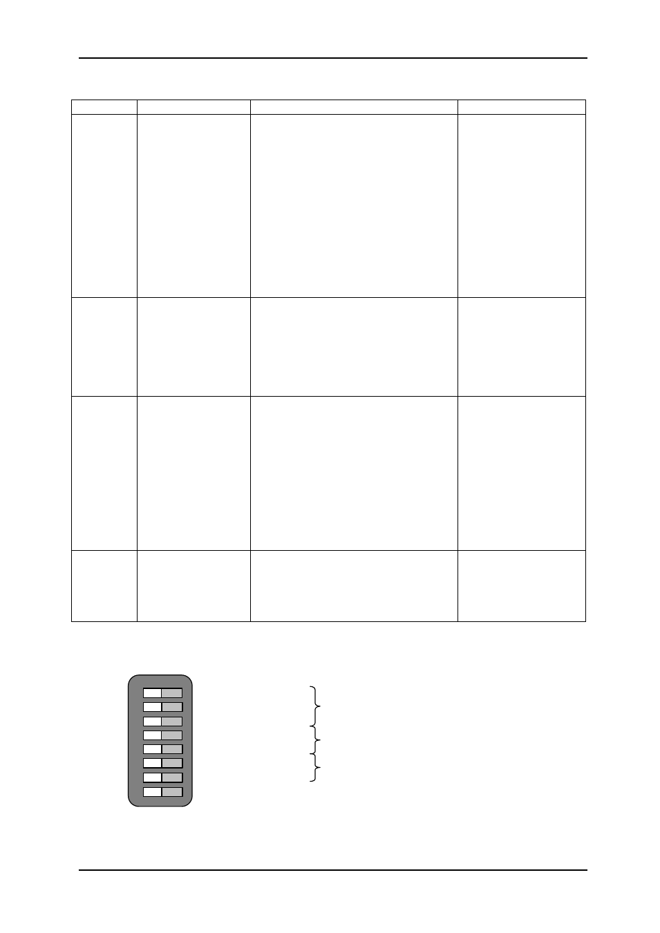
Switch 1 (’off’ / 0)
Switch 2 (’off’ / 0)
Switch 3 (’off’ / 0)
Switch 4 (’off’ / 0)
Switch 5 (’off’ / 0)
Switch 6 (’off’ / 0)
Switch 7 (’off’ / 0)
Switch 8 (’off’ / 0)
Routing
Shown: 1=>1 , 2=>2 , 3=>3 , 4=>4
Input Select
Shown: Auto, priority optical
Output Select (when no input)
Shown: black picture, auto video standard
Mode. Shown: GYDA control enabled
(Upper left corner of board)
OFF ON
1
2
3
4
5
6
7
8
Figure 9: DMUX DIP switches exemplified