D *event input configuration, Event input configuration, Figure 27: *event cable wiring diagram – NavCom SF-2110 Rev.C User Manual
Page 81: Table 14: *event wiring connections, D ..................... *event input configuration
SF-2110 User Guide – Rev. C
D ..................... *Event Input Configuration
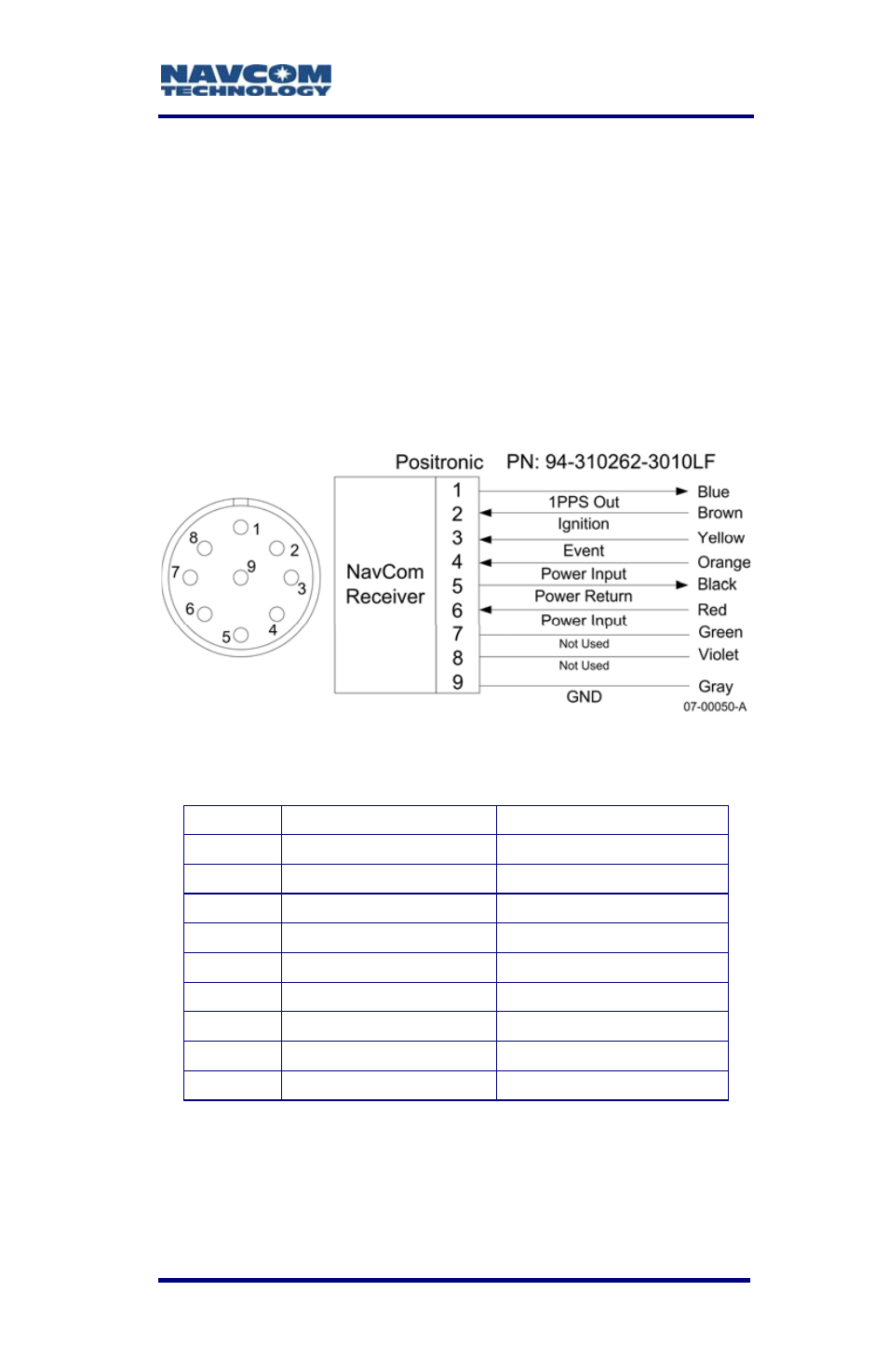
Figure 27 details the wiring of the Event/Can cable
assembly NavCom part number
P/N 94-310262-3010LF.
Refer to Chapter 2, Event section for detailed
electrical specifications.
Table 14 details the wiring configuration required for
Event-Hi, and Event-Lo pulse sensing.
Figure 27: *Event Cable Wiring Diagram
Table 14: *Event Wiring Connections
Pin # Signal Name
Color
1 *1PPS
Out
Blue
2 Ignition
Brown
3 *Event
Yellow
4 Power
Input
Orange
5 Power
Return Black
6 Power
Input
Red
7 Not
Used
Green
8 Not
Used
Violet
9 GND
Gray
Once the cable is wired to correspond with the event
pulse requirements, configure the receiver to output
the message containing a time mark, referenced to
* Consult Release Notes on the NavCom web site for availability.
D-79