2 rear panel guide, 3 parameter display – MultiDyne CTV-2000-FTX Series User Manual
Page 8
CTV2000-FTX Series CATV Fiber Optic Transmitter Users’ Manual
8
Modulating level is 42dBmV, VFD would display “MOD LEVEL= 42dBmV” after operations shown
above. Please consult a MULTIDYNE engineer for help with this feature.
7 RF input test port:
Standard 75Ω style F-style test port for RF signal on-line test. Level tested from this
port is 20dB lower than the actual RF drive level to the laser.
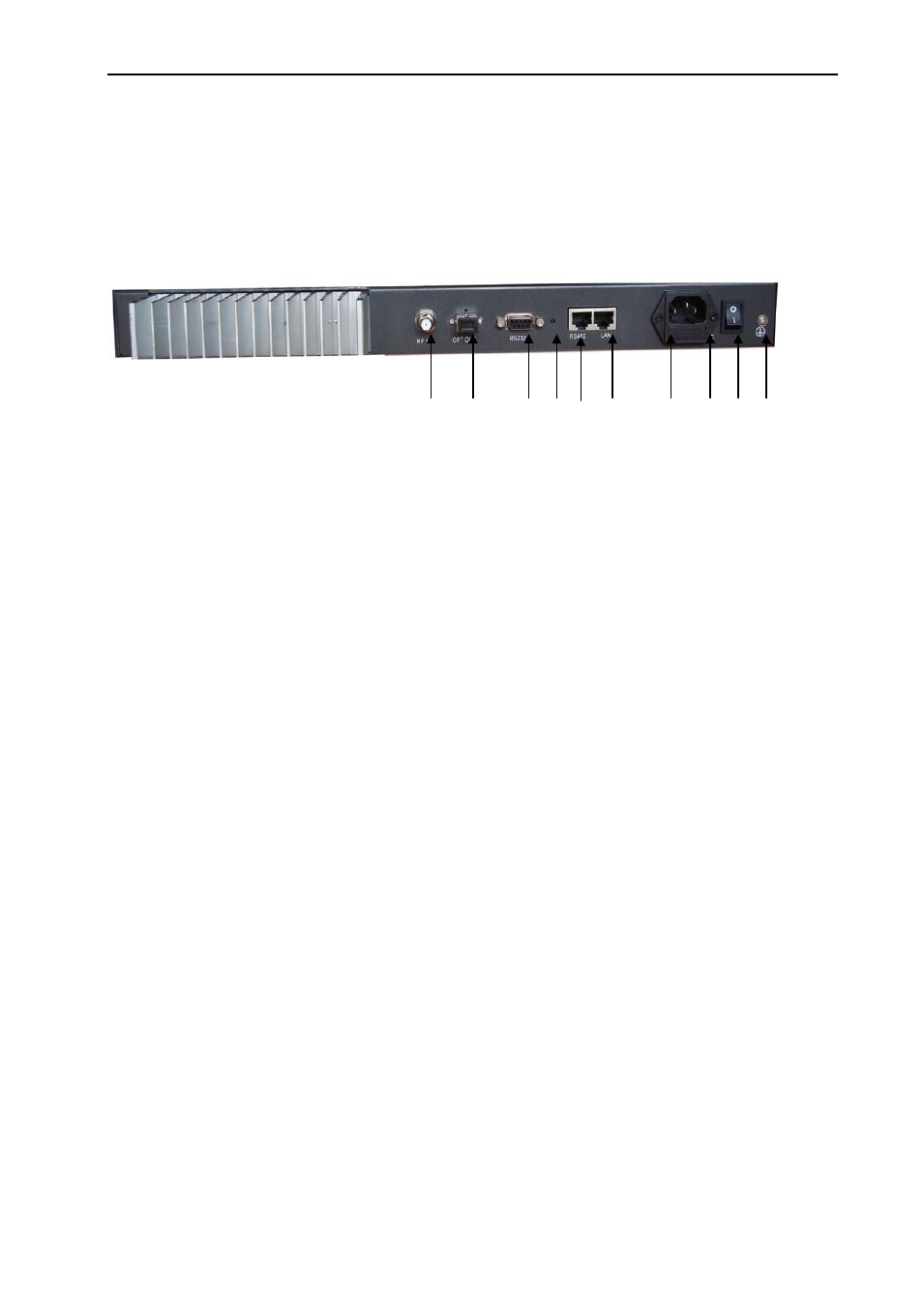
5.2 Rear Panel Guide
⑻ ⑼ ⑽ ⑾ ⑿ ⒀ ⒁ ⒂ ⒃ ⒄
Rear View
8 RF input port:
Standard 75Ω American style F port, used for connecting RF signal and the equipment.
Level in this input port must be at the range of 15~25dBmV. Too high level may damage laser. Optimum
input level is 17dBmV
9 Optical signal output: Optical signal output port, SC/APC, or optional FC/APC connector. There are
invisible laser emissions from Fiber output when laser is active!
*It would be dangerous to point this port toward the human body especially eyes when equipment is
energized!
10 RS-232 standard network management port: Use for connecting equipment with RS-232 port in
network management server.
11 Network management indicator
12 RS-485 standard network management port: Use for connecting equipment with RS-485 port on
network management server.
13 LAN network management port: Use for connecting transmitter with Ethernet-basing network
management server. (Contact factory for this option)
14 Power in: AC power connection.
15 Fuse
:AC fuse
16 AC Power switch: Turn ON or turn OFF the power.
17 Case grounding nut: Provided for optionally connecting the transmitter to ground.
5.3 Parameter Display
5.3.1 Turning on power display
When first turning on the power, the VFD will display ‘Initialize…’ for 2 seconds and the buzzer will
briefly tweet one time indicating that the transmitter has initialized successfully.
5.3.2 Status display