Section 6 trouble shooting, Trouble shooting procedure – MK Products Pulse+ User Manual
Page 17
Pulse+ Owner's Manual Page 17
Section 6
TROUBLE SHOOTING
SOME FACTORS TO CONSIDER:
The Pulse+ can only reduce the power supply output voltage and current, so
be sure the CV power supply is operating properly without the Pulse+.
The power supply sets the peak level and, therefore, must be set substantially
higher than non-pulsed operation.
When an arc is initiated, the Pulse+ is always in the pulse “on” mode to
provide maximum current to initiate the arc. After welding current is flowing, a
current switch is utilized to start the pulse timer.
If there appears to be too little output to weld with, be sure the pulse “on” is at
the proper value (or increase it) and that the pulse “off” is not excessive.
Be sure there is a good ground connection to the work and a good cable
connection to the Wire Feeder.
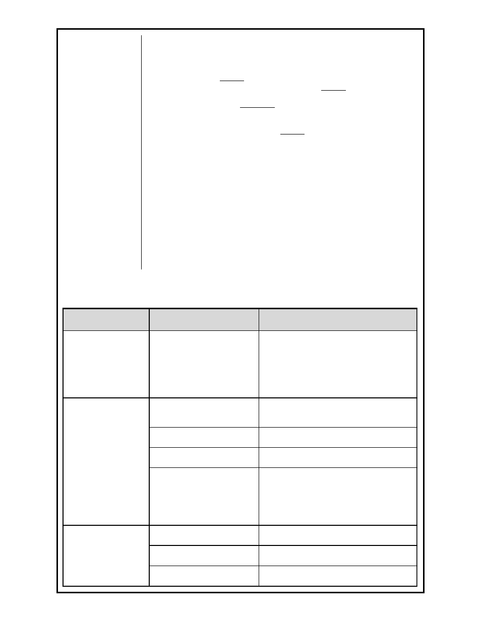
TROUBLE SHOOTING PROCEDURE
Trouble
Cause
Remedy/Explanation
Have welding output
but no pulse
Current switch failure or bad
PC board
The current switch, connected to J4, is
located on the negative buss bar next to the
capactitor bank. Disconnect J4 and short
between pins. If the unit now pulses,
replace the current switch. If it does not
pulse, check PC board.
Pilot lamp works , Fan
works, No weld output
J2 connector disconnected
from PC board
Replace J2 on board
Thermostat open
Check Thermostat for continuity
Power Supply voltage too low
Increase supply voltage
Open CR1 or R1, Bad PC
board
Disconnect 115 vac. With a ohm-meter
check resistance between input + and
output + terminals. Should read 5 ohms. If
open, check CR1 and R1 separate. If OK,
check PC board.
Completely Inoperative
Open line fuse (F1)
Replace fuse 2A 250V
Defective power switch (S1)
Replace switch
Improper line voltage
Check line voltage for 115vac