Section 21 testing the torch, 1 motor check, 2 testing the potentiometer – MK Products Prince XL/Spool Gun User Manual
Page 23: 3 testing the micro switch, W" clocked amphenol connector
Prince™ XL/Spool Gun - Owner's Manual Page 23
Section 21
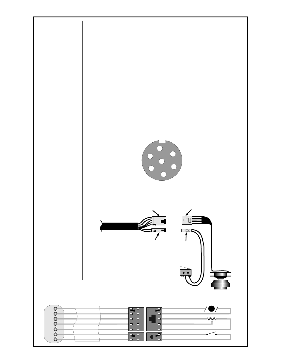
Testing the Torch
21.1 Motor Check
Remove the torch connector from the cabinet.
Using the torch Amphenol, check the resistance across pins “A” and “B”
(motor leads). The resistance across the motor should be between 5-10
ohms.
If an open circuit or short exist, check the motor leads and motor indepen-
dently.
21.2 Testing the Potentiometer
Using the torch Amphenol, check the resistance across pin “D” (wiper) and
pin “C”. The resistance should vary from 0 - 5K ohms.
Check the resistance across pin “D” (wiper) and pin “G”. The resistance
should vary from 5K - 0 ohms.
21.3 Testing the Micro Switch
Using the torch Amphenol, check for continuity across pins “E” and “F”
when the trigger is pressed.
E
C
A
B
D
G
F
+
-
TORCH
MOTOR
TORCH
POT
TORCH
TRIGGER
5K
Red
Black
Blue
Yellow/Orange
Brown
White
Green
Red
Grey
Grey
1
3
2
Grey
Grey
Red
Red
Pin 1
Pin 1
Pin 1
Pin 1
Cabinet End
Amphenol Connector
Torch Connectors
Inside Handles
Torch Functions
Torch Lead
Electric Cable
2 Pin Female Connector
P/N 153-0856
5 Pin Female Connector
P/N 153-0857
Male pins (7 total)
P/N 153-0852
2 Pin Male Connector
P/N 153-0854
5 Pin Male Connector
P/N 153-0855
Female pins (7 total)
P/N 153-0853
A
F
G
E
D
C
B
"W" Clocked
Amphenol Connector
Viewed from front of connector