Volt meter, Input / output configuration for tb1 – MK Products MK Cobramatic Pro Series User Manual
Page 37
Cobramatic
®
Pro Series Owner’s Manual - Page 30
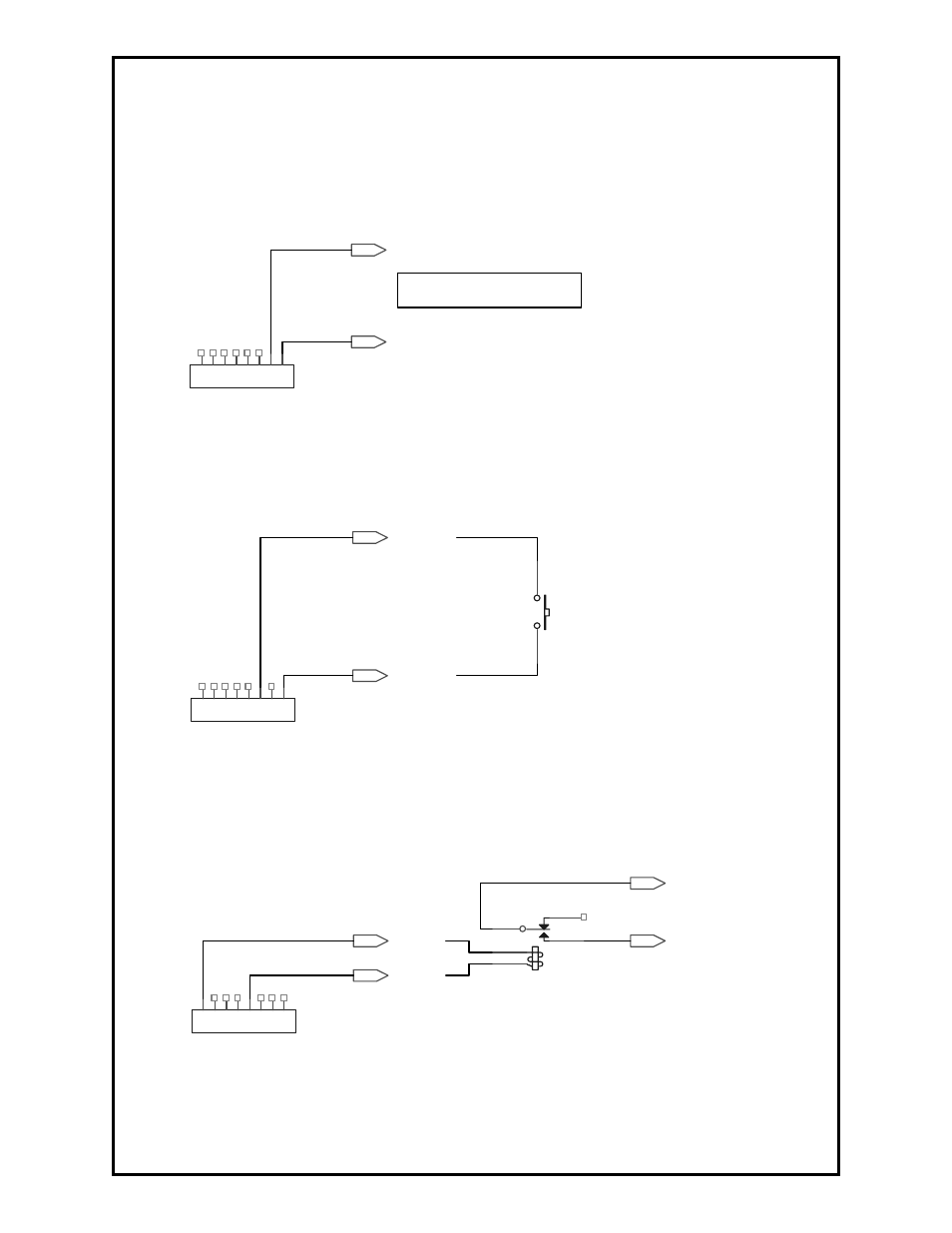
INPUT / OUTPUT CONFIGURATION FOR TB1
Monitor Wire Feed Speed
Use digital volt meter between: TB1 – 1(GND) and TB1 – 2(MSPD).
Measured value defined as: Reading x 100 = Wire Feed Speed.
Example: 3.54 VDC is equivalent to 354 IPM
GND
MSPD
TB1
1
2
3
4
5
6
7
8
VOLT METER
Remote/External Trigger
Install jumper between: TB1 – 1(GND) and TB1 – 3(TRIG) to trigger system.
GND
TRIG
TB1
1
2
3
4
5
6
7
8
SW
Arc Establish Relay Closure
External Contact Signal; Connect 24VDC relay coil between TB1 – 8 (24V)
and TB1 – 4 (ARC). When arc is established, the relay coil will close.
24V
ARC
ARC ESTABLISHED
ARC ESTABLISHED
TB1
1
2
3
4
5
6
7
8
K?
ARC ESTABLISHED RELAY
See also other documents in the category MK Products Equipment:
- CobraTig 150 XM (32 pages)
- CobraCooler (20 pages)
- Advanced Color Logic Rev.A (55 pages)
- Advanced Color Logic Rev.A (55 pages)
- DiamondBack Weldhead (30 pages)
- MiniMicro Orbital Weldhead (30 pages)
- Copperhead Weldhead (42 pages)
- Python Gun (37 pages)
- Python MM Com ACWC (43 pages)
- CobraMAX (28 pages)
- Cobra SX (28 pages)
- Cobra MX (41 pages)
- Prince XL Spool Gun (41 pages)
- Prince XL LE Com ACWC (41 pages)
- Prince SG (30 pages)
- WC-1-110 (26 pages)
- MK200 (20 pages)
- Sidewinder (26 pages)
- Weld Control (45 pages)
- Python LX Euro (41 pages)
- Python LX LE Com ACWC (41 pages)
- Prince XL Fronius Com ACWC (39 pages)
- Cobra SX Fronius Com AC (30 pages)
- Cobra MX MM Com ACWC (41 pages)
- Cobra SX MM Com AC only (30 pages)
- Positioner 1/AirCrafter T-25 (17 pages)
- Prince XL MM Com ACWC (39 pages)
- CobraTurn Digital Turntable (23 pages)
- CobraCooler 2003 (15 pages)
- CobraCooler 2005 (14 pages)
- Cobramatic II (45 pages)
- Cobramatic 120VAC (47 pages)
- Cobramatic 42VAC (38 pages)
- Cobramatic 120 VAC V6 (40 pages)
- CobraMig 260 PS/Feeder (62 pages)
- Cobra System III Gooseneck (26 pages)
- Prince XL/Spool Gun (41 pages)
- Cobra Gold Gooseneck (41 pages)
- RoboKing (33 pages)
- Python Rev.D (40 pages)
- Cobra MX Gun - ACWC (36 pages)
- Positioner #3 (14 pages)
- Positioner #2 (15 pages)
- MK 2000A (29 pages)