Appendix, 10 /100base-tx pin outs, 10/100base-tx cable schematic – Microsens MS453510 User Manual
Page 18
14
Appendix
10 /100BASE-TX Pin outs
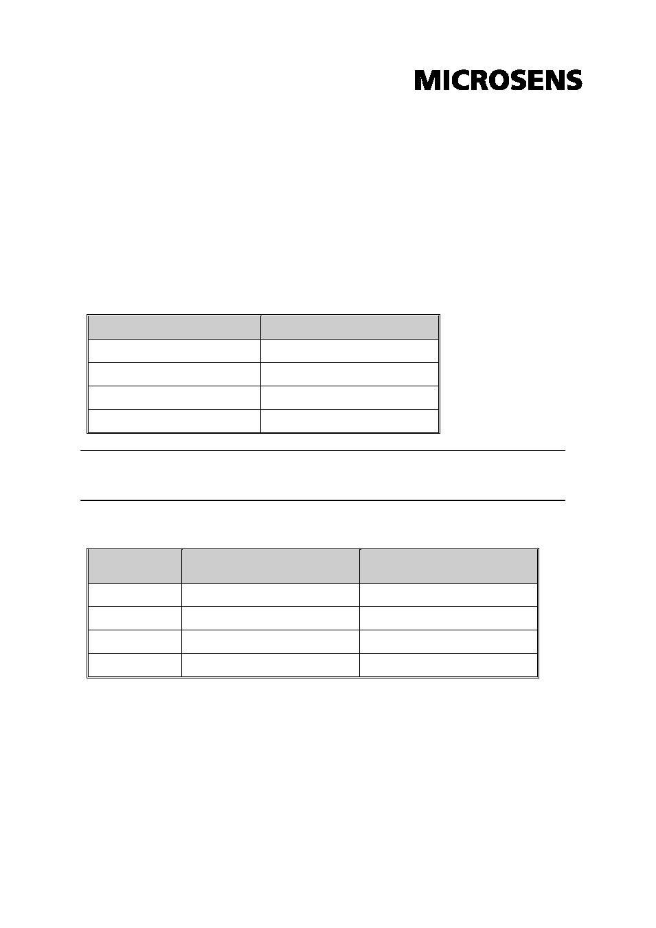
With10 /100BASE-TX cable, pins 1 and 2 are used for transmitting data, and pins
3 and 6 for receiving data.
RJ-45 Pin Assignments
Pin Number
Assignment
1
Tx+
2
Tx-
3
Rx+
6
Rx-
[NOTE] “+” and “-” signs represent the polarity of the wires that make up each
wire pair.
The table below shows the 10 / 100BASE-TX MDI and MDI-X port pin outs.
Pin MDI-X
Signal Name
MDI Signal Name
1
Receive Data plus (RD+)
Transmit Data plus (TD+)
2
Receive Data minus (RD-)
Transmit Data minus (TD-)
3
Transmit Data plus (TD+)
Receive Data plus (RD+)
6
Transmit Data minus (TD-)
Receive Data minus (RD-)
10/100Base-TX Cable Schematic
The following two figures show the 10/100Base-TX cable schematic.
See also other documents in the category Microsens Accessories communication:
- Gigabit Ethernet 6 Port Office Switch manageable with PoE or PoE+ (1 page)
- Gigabit Ethernet 6 Port Office Switch manageable with PoE or PoE+ (1 page)
- Gigabit Ethernet 6 Port Office Switch manageable with PoE or PoE+ (1 page)
- Fast Ethernet Micro Switch Twisted Pair Uplink Installation (6 pages)
- MS453081PM (2 pages)
- Fast Ethernet Desktop Switches (4 pages)
- MS453490M Installation (70 pages)
- MS655102/12x (22 pages)
- MS453510M (42 pages)
- MS655104 (26 pages)
- MS655100PX-48 (20 pages)
- MS655060-562P (22 pages)
- MS655200 (21 pages)
- MS655210 (7 pages)
- Ethernet Media Converter in industrial design (7 pages)
- MS655208 (21 pages)
- MS655060-562 (24 pages)
- MS655020X (9 pages)
- Gigabit Ethernet 3-port Converter Module 1000Base-T/X (4 pages)
- Fast Ethernet 2 Port Multifunction Bridge (8 pages)
- Gigabit Multimode Extender (2 pages)
- MS655099 (28 pages)
- MS400229 (7 pages)
- MS400082 (12 pages)
- MS400221 (16 pages)
- MS400089 (10 pages)
- MS400080H (11 pages)
- MS400191 (8 pages)
- MS400230 (10 pages)
- MS40016X (13 pages)
- MS40020x (16 pages)
- RS-485 (9 pages)
- MS550021-EU (6 pages)
- Passive 8 Channel CWDM DeMUX Module (3 pages)
- Modular Enterprise Chassis 4 HU (8 pages)
- MS655033X (20 pages)
- MS400920 (7 pages)
- MS400930 (7 pages)
- MS400934 (9 pages)
- MS400900M (42 pages)
- MS400940 (7 pages)
- MS400941 (7 pages)
- ATEX SFP-Transceiver (2 pages)
- MS453522M (237 pages)