Configuration, Setting the base address – Meinberg VME31 User Manual
Page 7
7
Configuration
Before the board can be installed in the VME bus rack, some jumpers must be
configured as described below. The location of the jumpers can be seen from the
component layout at the end of this manual.
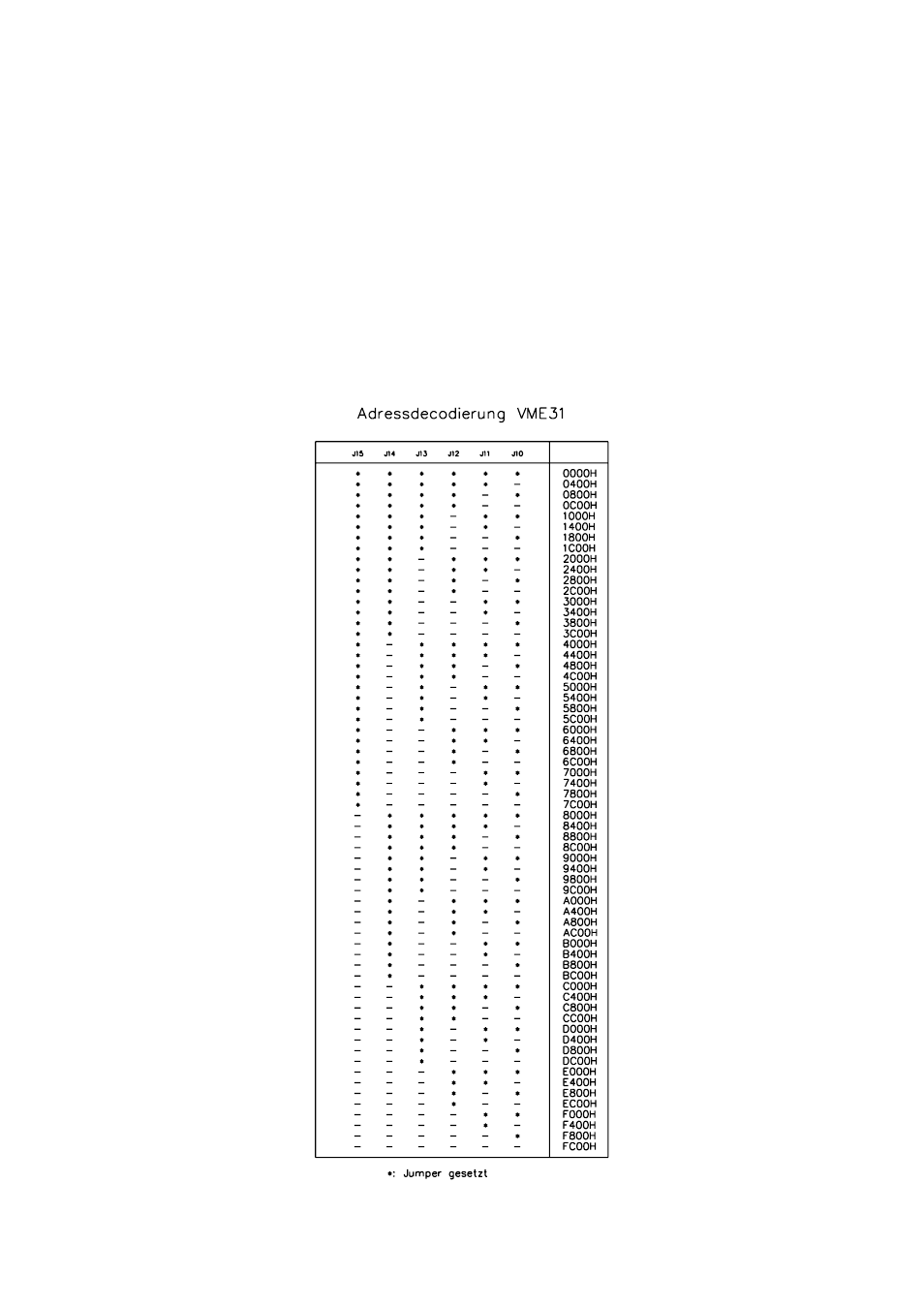
Setting the Base Address
The base address of the dual port RAM on the board must be configured correspon-
ding to the table shown below:
See also other documents in the category Meinberg Hardware:
- SHSPZF LANTIME (153 pages)
- SHSPZF LANTIME (132 pages)
- GPS180 (68 pages)
- GPS167LCD-MP (48 pages)
- GPS164xHS (34 pages)
- GPS163TDHS (34 pages)
- DCF77C51 (20 pages)
- C28COM (22 pages)
- SyncBox PTPv2 (32 pages)
- DU70 (20 pages)
- UA509P (36 pages)
- VP100 20NET (25 pages)
- DU35S (18 pages)
- VP100 20 (22 pages)
- SDU (14 pages)
- FM614 (8 pages)
- RU226 (4 pages)
- GEN170TGP (30 pages)
- DCF77 PCI511 (22 pages)
- TCR167PCI (36 pages)
- TCR511PEX (20 pages)
- GPS169PCI (34 pages)
- DCF77 PC32E (22 pages)
- TCR510PCI (20 pages)
- USB 5131 (12 pages)
- TCR51USB (15 pages)
- GPS167PC (28 pages)
- PZF510 (26 pages)
- PZF511 (36 pages)
- PZF600 (40 pages)
- FDM509 (20 pages)
- FDM511 (26 pages)
- GPS161 (30 pages)
- GPS162 (30 pages)
- TCR510 (28 pages)
- TCR509 (22 pages)
- TCG511 (22 pages)
- DCF77 UA509 (22 pages)
- UA32S (24 pages)
- NUC80E (20 pages)
- GPS L1 (3 pages)
- DOAL (10 pages)