Connectors and leds in the rear panel – Meinberg DCF77PC32 User Manual
Page 9
9
The computer has to be turned off and its case must be opened. The radio remote clock
might be installed in any slot not used yet. The rear plane must be removed before the
board can be carefully plugged in. The computer´s case should be closed again and the
antenna connected to the PC32´s coaxial plug at its rear. After the computer has been
restarted, the utility PCPSINFO.EXE should be run in order to position the antenna
(see below).
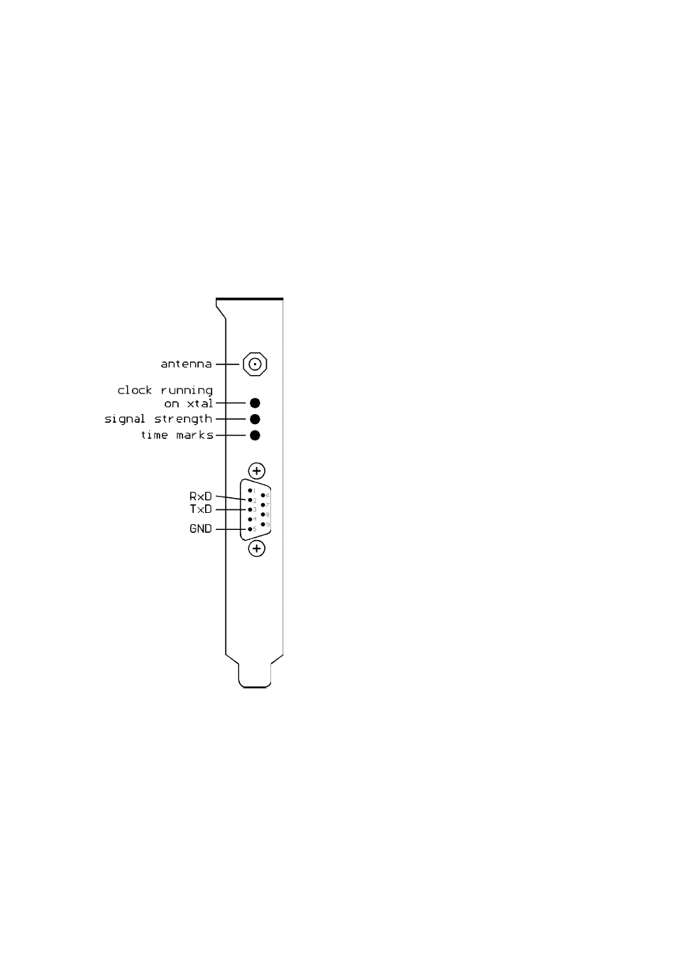
Connectors and LEDs in the Rear Panel
Three status LEDs and a 9 pin sub D connector
can be found in the rear panel (see figure be-
low). The LEDs let the user check for proper
receiver operation. The upper, red LED is on if
the clock is running on xtal. This LED can only
change when the minute changes (seconds incre-
ment from 59 to 0). The brightness of the LED
in the middle depends on the strength of the RF
signal. The lower, green LED should be blin-
king exactly once per second corresponding to
the time marks from DCF77. If this LED flashes
there is some electrical noise around which pre-
vents the receiver from decoding the time marks
and synchronizing. All information given by
these LEDs can also be obtained from the screen
of the program PCPSINFO.EXE.
The 9 pin sub D connector is wired to the
PC32's serial port. Pin assignment can be seen
from the figure beside. This port can not be used
as serial port for the computer. Instead, the clock
uses the port to send out Meinberg's standard
time string in order to control an external dis-
play or some other external device. The string is
sent out once per second, once per minute or if
requested by an incoming ASCII '?'. Starting
with EPROM version 3.2 it is also possible to
change the PC32's board time by sending such a
string to the board. Transmission speed, framing, and mode of operation can be
modified using the program PCPSINFO. The string format is described in the section
'Technical Specifications' at the end of this manual.