Specifications, Counter, Interrupts – Measurement Computing CIO-CTR10 User Manual
Page 14: Digital input / output
14
Chapter 3
Specifications
All specifications are subject to change without notice.
Typical for 25 °C unless otherwise specified.
Specifications in italic text are guaranteed by design.
Counter
Refer to the CTS9513-2 data sheet for complete 9513 specifications and operating modes. The data sheet is
available on our web sit
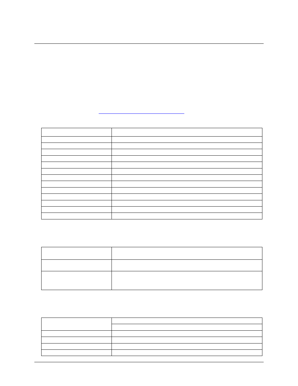
Table 1. Counter specifications
Parameter
Conditions
Counter type
9513
Configuration
Two 9513 devices. Five up/down counters per 9513, 16-bits each.
Clock input frequency
7 MHz max
X2 clock input source
1 MHz (10 MHz Xtal divided by 10)
High pulse width (clock input)
70 ns min
Cycle time (clock input)
145 ns min
Gate pulse duration
145 ns min
Input low voltage
–0.5 V min, 0.8 V max
Input high voltage
2.2 V min, 5 V max
Output low voltage
0.4 V max @ 3.2 mA
Output high voltage
2.4 V min @ –200 µA
Crystal oscillator frequency
10 MHz
Frequency accuracy
100 ppm
Interrupts
Table 2. Interrupt specifications
Number of interrupts
J2: 2 to 7, jumper selectable
J3: 2 to 7, jumper selectable
Interrupt enable
External, enabled with TTL low level on IR_A ENABLE (P1) and
IR_B ENABLE (P2)
Interrupt sources
External
J2 sets the IR_A INPUT pin (P1)
J3 sets the IR_B INPUT pin (P2)
Digital input / output
Table 3. Digital I/O specifications
Digital type
Output: 74ACT273
Input:
74LS373
Configuration
2 banks of 8 as output, 2 banks of 8 as strobed input
Number of I/O
16 input, 16 output
Output high
2.7 volts min @ –0.4 mA
Output low
0.5 volts max @ 8 mA