Measurement Computing Net232 User Manual
Page 10
10
Net232 User’s Guide,
1037-0901, rev 2.0
If connecting Net232 directly to your PC’s ETHERNET Port
:
Most users connect Net232 to an ethernet hub. This portion of step 3 applies only to
users wanting to connect Net232 directly to their PC.
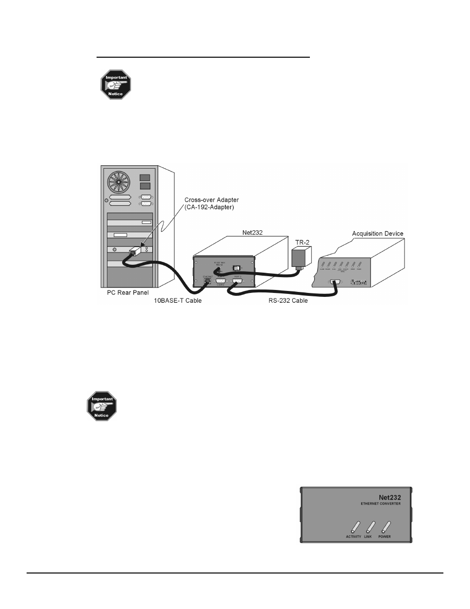
(a) connect the cross-over adapter (CA-192-Adapter) to your PC’s ethernet connector
(b) connect the “straight-through” 10BASE-T cable (CA-192-5) to the cross-over adapter
(c) connect the other end of the straight-through cable to Net232’s ETHERNET Port
Option: A 10BASE-T cross-over cable may be used in place of the adapter/straight-through cable.
Connecting Net232 Directly to a PC
Note: When connecting Net232’s CA-192-5 ethernet cable directly to a PC, a cross-over adapter
(CA-192-Adapter) must be used.
4. Plug power adapter TR-2 into Net232’s power connector (located on the rear panel). Plug the prong
end of the adapter into an appropriate power receptacle.
5. Power-up your acquistion device. The Power LED should light up.
6. Turn Net232’s power switch to the “1” (ON) position. The Power LED should light up.
At initial power-up your acquisition device performs automatic self-tests to ensure it is
fully functional. ChartScan, MultiScan and TempScan units contain rear panel LEDs
that will indicate errors, should they occurr. Possible error conditions and their
corresponding indicator light patterns are shown in your device user’s manual.
If no problems are found, your acquisition device will begin a power-up initialization. This self-test is
performed each time the unit is powered up regardless of whether power-on was caused by the power switch
or the Power-On Reset (
*R
) command.
The self-test takes approximately 5 seconds to complete.
Net232 contains 3 indicator LEDs. These indicators have the
following meanings when lit:
ACTIVITY – Data is being transmitted over the ethernet.
LINK – There is a good connection to the ethernet.
POWER – Net232 has power.
Net232 Front Panel