Software setup – Measurement Computing DBK12 User Manual
Page 4
DaqBook/100 Series & /200 Series and DaqBoard [ISA type] Configuration
Use of DBK12 or DBK13 requires the following setup steps for DaqBook/100 Series & /200 Series
devices and DaqBoard [ISA type] applications.
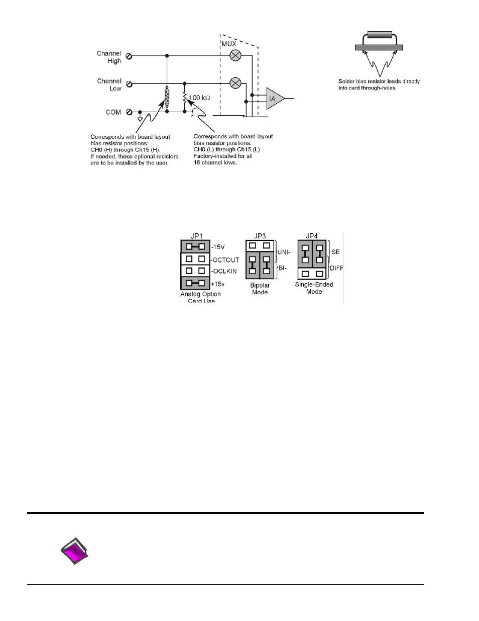
1. If not using auxiliary power, place the JP1 jumper in the expanded analog mode.
Default Configuration Settings for DBK12 and DBK13
Note: These jumpers are located in the DaqBook/100 Series & /200 Series devices and
DaqBoard [ISA-Type] units.
The JP1 default position, indicated in the above figure, is necessary to power the interface circuitry
of the DBK12 or DBK13 via the internal ±15 VDC power supply. If using auxiliary power (e.g. a
DBK32A or DBK33), you must remove both JP1 jumpers. Refer to Power Requirements in the
DBK Basics section and to the DBK32A and DBK33 sections as applicable.
2. For DaqBook/100, DaqBook /112, and DaqBook /120 only, place the JP3 jumper in either the
unipolar or bipolar mode as needed (bipolar shown).
3. For DaqBook/100, DaqBook /112, and DaqBook /120 only, place the JP4 jumper in the
DaqBook/DaqBoard in single-ended mode.
Note: Analog expansion cards convert all input signals to single-ended voltages referenced to
analog common.
DaqBook/2000 Series and DaqBoard/2000 Series Configuration
No jumper configurations are required for these 2000 series devices.
Software Setup
Reference Notes:
o
DaqView users
-
Refer to
chapter 3, DBK Setup in DaqView.
o
LogView users - Refer to chapter 4, DBK Setup in LogView.
DBK12 and DBK13, pg. 4
879895
DBK Option Cards and Modules